• Welcome to RCCrawler Forums.

    It looks like you're enjoying RCCrawler's Forums but haven't created an account yet. Why not take a minute to register for your own free account now? As a member you get free access to all of our forums and posts plus the ability to post your own messages, communicate directly with other members, and much more. Register now!

    Already a member? Login at the top of this page to stop seeing this message.

Jato Repents with a VS4-10 Origin Limited Kit

Why do servo manufacturers insist on using Phillips head screws to attached the servo horn? For the most part, RC manufacturers have switched exclusively to Allen or hex head screws, except for you Tamiya :flipoff:, but the servo horn screw is always Phillips. Does anybody know the reasoning for this? There has to be some history here.

They are just M3 screws, use a hex head one.

Tough problems call for tough solutions. "thumbsup"
 
They are just M3 screws, use a hex head one.

Tough problems call for tough solutions. "thumbsup"

:lmao: I know you can switch out the screw. Sometimes I do and sometimes I don't. But the question remains...why do they do it?

Besides, I need a reason to keep my Phillips head screwdrivers...
 
Last edited:
....OSRC told me that I needed to trade in the Thanksgiving tablecloth for a Christmas one, but I said this is fall themed and it's technically still fall. :lmao:


You got three days.. Then its time to put the cornflakes on some snowflakes. (The good kind, not the whiny kind)
 
:lmao: I know you can switch out the screw. Sometimes I do and sometimes I don't. But the question remains.

I need a reason to keep my Phillips head screwdrivers...

Probably because Futaba included Phillips screws with their servos 40 years ago and things never change.

My Phillips screw drivers have been relegated to the general tool box away from the RC stuff. It makes me irrationally angry when I have get up and go find a Phillips driver for like 2 screws out of a whole truck. :lmao:

Yeah it also annoyed me to have to get up and dig through my RC bag just to find a Phillips screwdriver for a one-time use.
 
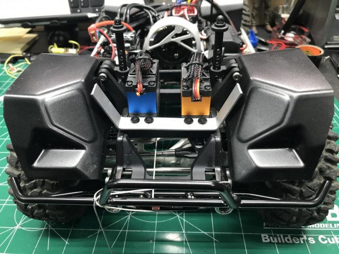
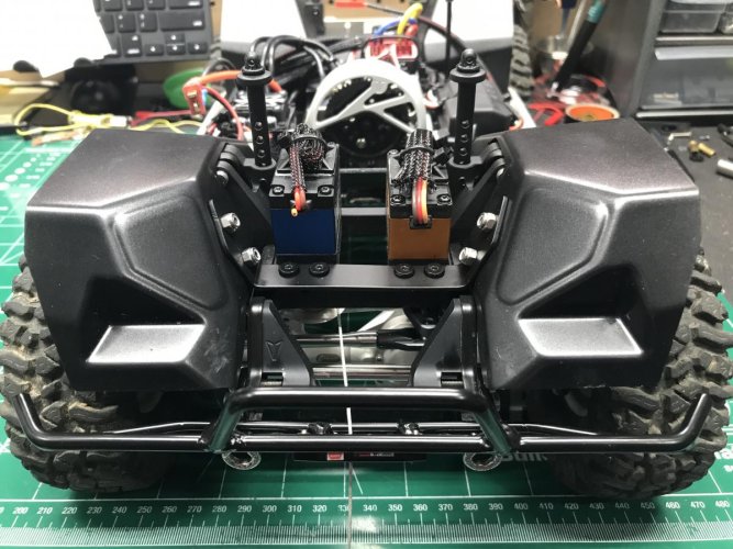
For the front I'm using very short body posts. The rear is one size and it's definitely going to have to be cut down to allow the body to sit lower. Did you guys have to trim your body posts to get the body to sit low enough?

That's odd, I don't remember having to cut my rear body post down.:shock: I'll have to go back and take a look at mine.

Oh and my servo horn is slightly turned toward the driver side too on both my Origin and PRO. I was worried that it might affect the steering, but the servo does turn lock to lock without any issues!

If I look down in the body post holes on the shock tower I see the frame rails. This is what stops my body posts from going in farther.
 
The body post height suggested in the manual will place the body exactly where it needs to be to line up in the sliders and rest cleanly against the bumpers with the factory body trim.

If you want to trim it further, then yes, you can modify as you see fit.
 
The body post height suggested in the manual will place the body exactly where it needs to be to line up in the sliders and rest cleanly against the bumpers with the factory body trim.

If you want to trim it further, then yes, you can modify as you see fit.

I completely forgot that this body ties into the sliders. Good thing I didn't cut the body posts in advance.
 
What is the stock spur and pinion sizes? Also, what would you recommend to tame the ROC412 a little bit? It seems like it's going to be too fast and too touchy for my kind of scale crawling.
 
I can't remember off the top of my head the sizes of spur and pinion. Maybe somebody else can chime in.

I run the Mamba X with the 3800kv Slate in mine and I set a throttle curve to tame mine down. The curve is set up to give me super smooth and slow low end while maintaining the top end when needed. It was the first time I messed with throttle curve. It was pretty easy to do and gave me the results I was looking for. I also was able to keep the stock spur and pinion (what ever it is).
 
Last edited:
Pretty sure the stock gearing is 54/13.

I ended up using 54/12 when running the Puller Pro 2700kv and changed to 56/9 when the PP 3500kv went in.
 
What is the stock spur and pinion sizes? Also, what would you recommend to tame the ROC412 a little bit? It seems like it's going to be too fast and too touchy for my kind of scale crawling.

13/54. What ESC and transmitter? That ROC412 should have plenty of low end with that gearing.

Final drive is 40.5:1. Much lower than most kits on the market. 11/56 would net you a 50:1 ratio if the top end is too much.

I've been running 2300KV roc 412's for a while now. Works great on 3S and if I am testing parts or know I will want some extra wheel speed it handles 4S really well.
 
I can't remember off the top of my head the sizes of spur and pinion. Maybe somebody else can chime in.

I run the Mamba X with the 3800kv Slate in mine and I set a throttle curve to tame mine down. The curve is set up to give me super smooth and slow low end while maintaining the top end when needed. It was the first time I messed with throttle curve. It was pretty easy to do and gave me the results I was looking for. I also was able to keep the stock spur and pinion (what ever it is).

Every once in a while I'll mess with throttle curves in the ESC, but I much prefer linear curves. I prefer my trigger finger to control the throttle curve.


Pretty sure the stock gearing is 54/13.

I ended up using 54/12 when running the Puller Pro 2700kv and changed to 56/9 when the PP 3500kv went in.

Thanks for the info.


13/54. What ESC and transmitter? That ROC412 should have plenty of low end with that gearing.

Final drive is 40.5:1. Much lower than most kits on the market. 11/56 would net you a 50:1 ratio if the top end is too much.

I've been running 2300KV roc 412's for a while now. Works great on 3S and if I am testing parts or know I will want some extra wheel speed it handles 4S really well.

Thanks.

I'm not worried about low end power. I know the ROC will have plenty of that. I'm more worried about slow speed control and taming the relatively quick motor.

I'll be using the Mamba X with 3S. Transmitter will be the FlySky GT5.

Why did you choose the 2300kv over a higher kv?
 
I ordered a 10T instead of an 11T by mistake. Might be a little too slow, but maybe not.
 
Next up for the Origin is to install the inner fenders. I was able to paint them in my basement with Pactra black. This is the first time I'm using Pactra paints. I don't know if it's always been made by Rust-Oleum, but apparently it is now.

I painted these fenders with 3 or 4 heavy coats and I still had light spots. But I figured you shouldn't be really notice them out on the trails so I continued once the paint was dry.


Peeling the protective film off of the inner fenders was a PITA. It kept tearing no matter how meticulous I was. Usually, peeling this film is a fun and satisfying task, but not here. It's an exercise in frustration. I hope the body film isn't like this!


The inner fenders weren't cut as closely to the chassis lines as I expected. Here you can see a relatively large gap between the inner fender and the frame rails. I wish the fit was better all around.

Initially, each inner fender only mounts to the frame on one end using two screws. They are very flimsy and flop around everywhere at this point.

I did have to remove the front bumper here to install the front inner fenders. The aluminum frame brace insert made me think it was OK to install the front bumper at that stage, but you should wait. Not a big deal though as it's only four screws.

You also install the rear bumper while installing the rear, inner fenders.


Here are the great looking sliders with the metal "tabs" attached. These tabs will later be used to locate the sides of the body. The tabs are raw aluminum and they don't match the sliders, but you won't see them once the body is installed.


The sliders oddly have holes in the outsides of them. Two holes on each slider line up with the mounting screws. Without these thru holes you'd have to use a very short driver or an L-wrench so, thankfully, you can use your standard hex drivers here. I'm assuming the need for accessing the mounting screws is what spawned the hole pattern in the sides of the sliders in the first place.


The sliders do look great once installed.


While assembling the chassis you install these two, plastic mounts. I had the foresight to leave them loose knowing that whatever gets attached may not lineup perfectly.


The massive battery and electronics mount is what gets attached the the plastic mounts seen above. I struggled to get those lined up with the battery tray. I had to really loosen the screws that attach those plastic mounts. After I did that everything lined up pretty well. This battery/electronics tray is very sturdy, but I think it's overkill. Plastic with similar thickness would have been just fine. I'd rather the mounts above be aluminum and this tray plastic, but that's just my two cents.


The instructions made me think for a second here because they appear to show another step, but really it just shows the battery tray installed. I can't remember anything else like this in the manual.


The battery tray is also used to mount the other ends of the inner fenders in place. After this, they are fairly sturdy.


The bottom of the floorboards are covered with these plastic pieces that I assume are made from Delrin. They are scratched all to hell out of the package. It's tough to see in the photo, but it looked like somebody had taken sandpaper to mine. It doesn't matter to me because this isn't going to be a shelf queen, but I did find it to be odd.


The manual tells you to attach these Delrin covers or sliders with M3 x 10mm screws, but M3 x 8mm screws were provided in my kit. 8mm is plenty long to attach these covers.


The Delrin covers get attached here to these raw, aluminum mounts on the chassis to which the aluminum sliders attach. Obviously, if you left these mounts uncovered they would be snag points.


This is where I ran into another issue. I must have gotten Monday or Friday mounts because the threads were machined like crap as you can see in the photos below. I do not have an M3 tap on hand (I should), so I had to use an M3 screw and turn it in with lots of force to clean up the threads.


Once I cleaned up the threads, I installed the Delrin covers.


Unfortunately, the fit isn't the best. These pieces aren't wide enough so you have to choose to leave a gap between them and the sliders or them and the frame. I pushed mine up against the sliders.

Also, as you can see here, the holes in the Delrin appear to be drilled too close together and this leads to some warping in the plastic. The Delrin also doesn't sit exactly flush with the bottom of the frame so you have a little lip here. All minor stuff, but I do think it's noteworthy.

Instead of these Delrin covers, I wish they would have integrated them into the mounts or made them wedge shaped to prevent these issues.


At some point while installing the battery tray or Delrin covers I wrecked the one inner fender. As you can see in the photo below, the Lexan spidered and broke clean off around the two mounting screws. I was so pissed off about this. I have no idea how it happened. I do know that there is no way this inner fender would have survived a tumble on the rocks if it couldn't handle being leaned on during the assembly. I am, at the least, partially to blame so I ordered a new set of inner fenders rather than contacting Vanquish.

It will be a semi-PITA the install because it's sandwiched between the slider and battery tray.


After installing all of this stuff, I noticed that there isn't much room between the tire and the slider.

I'm not sure you can get much larger tires on this truck without having to cut the pretty sliders.


In the bag of parts, Vanquish has included this plastic, bumper block off which is nice.


So that's it for now. Again, paint is the holdup. I've found a local guy that I may get to paint this body for me. Stay tuned.
 
To solve the inner fender tearing, make a styrene donut from stock. I did it on the wife’s Enduro inners, never painted them, so you can see the white squares, behind the red d rings
They fit under the screw heads and clamp the fenders in place.
273021f7f7c5c76254954f435587237e.jpg


Hang up and Drive
 
I had the same issue with the weird gap between the inner fenders and the frame rails. VP fixed this issue with the PRO kits. The gap is no longer there. I believe they are the same fender kit, but just lazer cut different.

That's odd about the delrin skids. Mine bolted up perfectly. They lay nice and flush and smooth. I also did not have any issues with any bolt threads in the alum braces. All were drilled and taped nicely.

When I installed my front inner fenders to the chassis rails, I used washers under the screws to make them more secure so they wouldn't break. They ended up breaking anyways though.

Mike's idea with making the styrene piece will help keep them from breaking. I went a little overkill on mine and made an alum bracket to bolt into the fenders and I used the servo mount screws to attach it. Sprayed it with some black paint to blend in. It is rock solid now and is bullet proof!:)

IMG_2980.jpg

IMG_2988.jpg

IMG_2989.jpg
 
I went a little overkill on mine and made an alum bracket to bolt into the fenders and I used the servo mount screws to attach it.

I like that a lot. One of my inner fenders is broken off at the screw holes too. I may whip up something like this in Fusion 360 and 3D print a brace. It never dawned on me to try because I didn't care that much about it since it isn't going anywhere with the body installed, but this is a great solution.
 
Back
Top