• Welcome to RCCrawler Forums.

    It looks like you're enjoying RCCrawler's Forums but haven't created an account yet. Why not take a minute to register for your own free account now? As a member you get free access to all of our forums and posts plus the ability to post your own messages, communicate directly with other members, and much more. Register now!

    Already a member? Login at the top of this page to stop seeing this message.

B-MOW's Element GK-Ecto-Knightrunner Build

Ok, last update today. Probably the last until the weather gets warmer so that I can send the Knightrunner body to the paint shop (aka:outdoors).

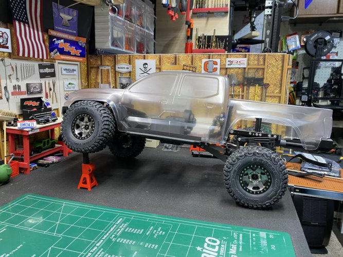
The Knightrunner body is cutout, trimmed and mounted. Everything lined up great and the body fits this GK chassis very good.

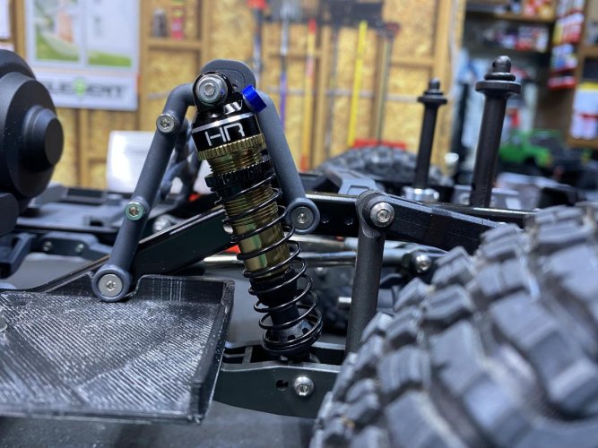
The rear shocks tuck in nicely inside the cab where the rear seats will be. Since the shocks are now located inside of the cab, I may in the future put the Knight Customs full drop bed in. I did buy the file and tried to print it, but I am having problems get the print to finish without having a bed full of spider web filament. Probably my fault and I need to figure out how to fix it.

Not that I wanted to, but I had to trim half of the fender flares so that the tires would not rub when the suspension was cycled and the front tires turned. I did add a 5mm spacer to the rear shock shafts and a 10mm spacer to the front shock shafts to limit the travel so that when suspension is bottomed out, the tires will stop just before hitting the bottom of the fender flares. Since I'm using the GKS trailing arms and the Knight Customs IFS lowering kit, I still have more than enough flex on all four corners. I forgot to snap a pic in a flex position, so I get one and post it later.
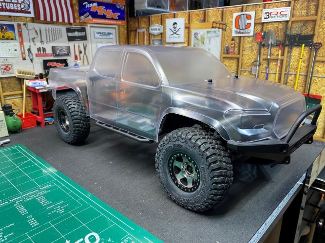
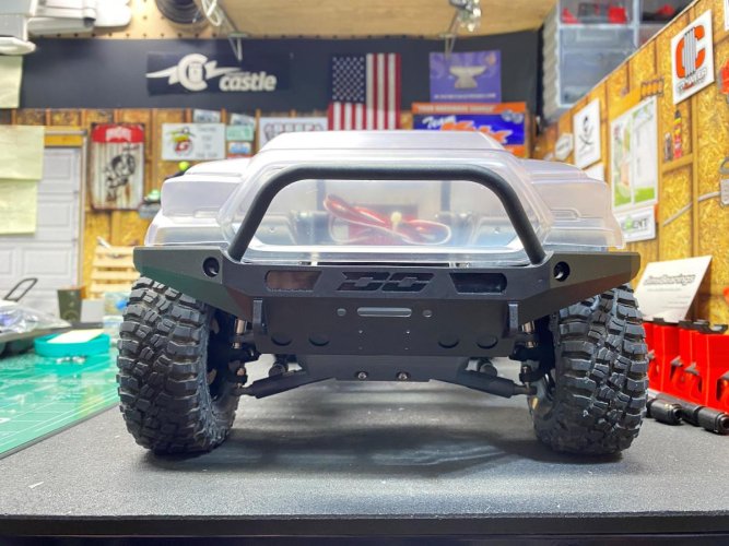
IMG_8425 (2).jpg

IMG_8426 (2).jpg


The next 2 pics show how the rear body post are attached. I think this will work out very well in supporting the rear of the body.
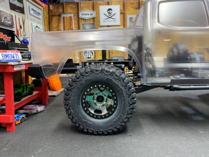
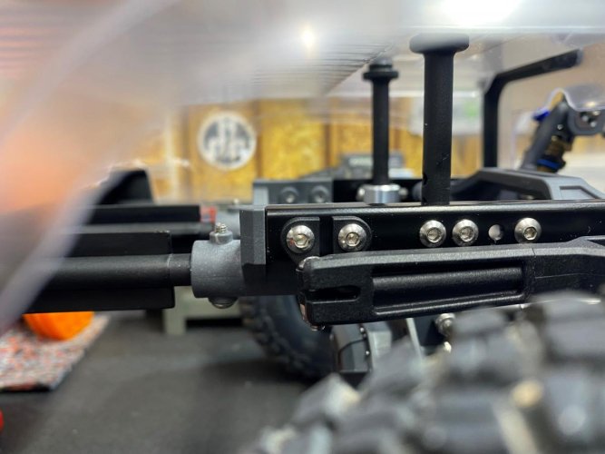
IMG_8427 (2).jpg

IMG_8429 (2).jpg


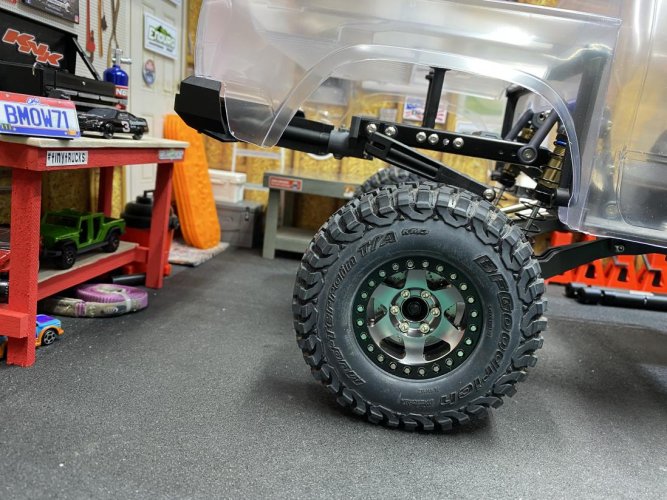
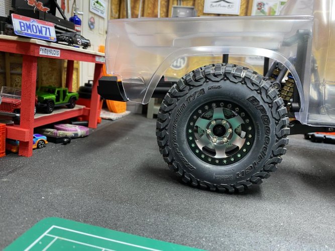
And the last 2 pics show off the wheels and tires I have chosen for this rig. The wheels are the common cheap Amazon wheels wrapped in the Pro-Line Class 1 BFG KM3's. I've had these set of tires for about 3 years now and they have finally found a home. I think they look great on these wheels and they go well with this Tacoma body.

Almost forgot to mention that I have also installed a set of stainless steel rotor/weights behind each wheel. I found these on Amazon. They have a decent amount of weight to them.

I picked up a few packs of the SSD scale hardware to replace the hex head screws on the beadlock. I still need to order a set of SSD scale acorn bolts for the lug bolts to finish the look.
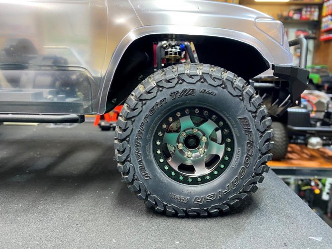
IMG_8428 (2).jpg

IMG_8421 (2).jpg

More to come as I tinker with the build and wait for better painting weather.
 
Everything looks PERFECT, man... "thumbsup"

Gotta love it when a build using so many non-standard parts comes together like that!
 
I agree, a drop bed would look sweet on there! It would fill in the gap nicely. Might have to watch the sway bar links though.

The KM3s look sweet with this body. I wasn’t getting much rubbing on Runner with the Tacoma body. How much is the difference in travel between the link and trailing arm setup?

This thing is looking awesome!!

BTW, is your body shop’s availability just as spotty as mine?


Sent from my iPhone using Tapatalk
 
It won't help you resolve the stringing issue with your future prints but I have a KC drop bed (two part, with "toolbox") printed already, just laying around if you're interested.

The paint needs work but I have no use for it myself. I could send it your way (or to anyone body else that might be looking) for the cost of shipping.
60308f1546dc197cf097ad6496723cf9.jpg


Sent from my LM-V600 using Tapatalk
 
Everything looks PERFECT, man... "thumbsup"

Gotta love it when a build using so many non-standard parts comes together like that!

Appreciate!"thumbsup""thumbsup"

Yeah, it's fun to mix and match and see what will fit and work together. And a huge relief when it all merges into one with very little headache:)!
 
I agree, a drop bed would look sweet on there! It would fill in the gap nicely. Might have to watch the sway bar links though.

The KM3s look sweet with this body. I wasn’t getting much rubbing on Runner with the Tacoma body. How much is the difference in travel between the link and trailing arm setup?

This thing is looking awesome!!

BTW, is your body shop’s availability just as spotty as mine?

Sent from my iPhone using Tapatalk

Thanks Phryo!"thumbsup"

Yeah, the drop bed will look good on there and your right, the sway bar links may be a problem. I'll have to take a closer look at that. Since I put spacers on the shock shafts, the sway bar may not go much above the chassis rails now. I'll have to confirm that later.

Availability is spotty and it sounds like I may be visiting the same body shop as you are!:lmao: I tell ya, I'm ready for warmer, dryer weather!
 
It won't help you resolve the stringing issue with your future prints but I have a KC drop bed (two part, with "toolbox") printed already, just laying around if you're interested.

Sent from my LM-V600 using Tapatalk

I greatly appreciate the offer. I'm going to try to reposition it and reprint it. If I can't get it to print and you still have the bed, I'll message you. Again, thanks for the offer.

I'm fairly certain my "ball of string" issue has something to do with the supports in the print. It would print fine until it got to a certain point, and just as luck would have it, it would happen while I wasn't around to see it. I'm not sure if it is possible, but I may try to cut the bed in half, reposition and print it again.
 
I greatly appreciate the offer. I'm going to try to reposition it and reprint it. If I can't get it to print and you still have the bed, I'll message you. Again, thanks for the offer.


I'm fairly certain my "ball of string" issue has something to do with the supports in the print. It would print fine until it got to a certain point, and just as luck would have it, it would happen while I wasn't around to see it. I'm not sure if it is possible, but I may try to cut the bed in half, reposition and print it again.
No worries. Figured I'd offer.

Like I said, I have no use for it but I'm also not actively trying to get rid of it. So unless somebody else reading this thread asks for it, it's not going anywhere.

Edit: Spelling. I shouldn't be posting when first wake in the morning.

Sent from my LM-V600 using Tapatalk
 
Last edited:
@Phyro asked this question a few post back: How much is the difference in travel between the link and trailing arm setup?

So I don't have or know how much travel the stock Knightrunner with links has, but I can show how much the GKS trailing arms have.

The first 2 pics show the rear suspension fully extended and at full compression. Keep in mind that I have 5mm spacers on the rear shock shafts to keep the tires from rubbing the body when fully compressed.

IMG_8438.jpg

IMG_8439.jpg


The next 2 pics show the front suspension fully extended and at full compression. I am using a 10mm spacer on the shock shafts to limit the travel so that the tires do not rub the body at full compression.

IMG_8435.jpg

IMG_8437.jpg


The next 2 pics show the front and rear tires fully compressed into the wheel wells. Using the shock shaft limiters, the tires tuck in nice without causing excessive body rub.

IMG_8441.jpg

IMG_8440.jpg


This full side shot shows how much flex I am getting with the shock limiters. IMO there is plenty of flex and there will be no worry of tire rub.

IMG_8442.jpg


These last 2 pics show the spacers and o-rings that I installed on the front and rear shock shafts. 10mm in the front and 5mm in the back.

IMG_8444.jpg

IMG_8445.jpg
 
@Phyro asked this question a few post back: How much is the difference in travel between the link and trailing arm setup?

So I don't have or know how much travel the stock Knightrunner with links has, but I can show how much the GKS trailing arms have.

The first 2 pics show the rear suspension fully extended and at full compression. Keep in mind that I have 5mm spacers on the rear shock shafts to keep the tires from rubbing the body when fully compressed.

View attachment 399926

View attachment 399927


The next 2 pics show the front suspension fully extended and at full compression. I am using a 10mm spacer on the shock shafts to limit the travel so that the tires do not rub the body at full compression.

View attachment 399928

View attachment 399929


The next 2 pics show the front and rear tires fully compressed into the wheel wells. Using the shock shaft limiters, the tires tuck in nice without causing excessive body rub.

View attachment 399930

View attachment 399931


This full side shot shows how much flex I am getting with the shock limiters. IMO there is plenty of flex and there will be no worry of tire rub.

View attachment 399932


These last 2 pics show the spacers and o-rings that I installed on the front and rear shock shafts. 10mm in the front and 5mm in the back.

View attachment 399933

View attachment 399934


Thank you so much for posting this!!! Looks like a nice increase in travel at the front and rear even with the spacers! I converted Runner last weekend to the standard Knightrunner. The rear tires never drop completely out like that. And I maybe have half of articulation you have! Never really see the front wheels get in the fender wells like that.

This is max for Runner. Bowhouse setup and linked rear.
6d549a87d847d31e63d35e5160328be8.jpg


Sent from my iPhone using Tapatalk
 

Personally, I prefer the flex on your truck. For an IFS I prefer it to be stiff to keep the center skid away from obstacles and have the rear suspension do most of the work. It's probably not ideal for performance but I prefer the way they drive.

Not that I see any issue with B-MOWs truck though.

Sent from my LM-V600 using Tapatalk
 
Edit: Spelling. I shouldn't be posting when first wake in the morning.

Sent from my LM-V600 using Tapatalk

Understood what you meant. You gotta love spell checker!:lmao:


Thank you so much for posting this!!! Looks like a nice increase in travel at the front and rear even with the spacers! I converted Runner last weekend to the standard Knightrunner. The rear tires never drop completely out like that. And I maybe have half of articulation you have! Never really see the front wheels get in the fender wells like that.

This is max for Runner. Bowhouse setup and linked rear.

Sent from my iPhone using Tapatalk

Your setup looks good. I didn't expect to see that much articulation with the stock links. I think the front tires entering the wheel wells on mine is mainly due to the Knight Customs lowering parts.

Nice looking paint job! It looks similar in color to what I have planned for mine so it will match my 1:1!;-)

Personally, I prefer the flex on your truck. For an IFS I prefer it to be stiff to keep the center skid away from obstacles and have the rear suspension do most of the work. It's probably not ideal for performance but I prefer the way they drive.

Not that I see any issue with B-MOWs truck though.

Sent from my LM-V600 using Tapatalk

I agree with what you are saying. My Trailwalker with IFS acts like you have described and it has been fun to drive.

I am liking what I'm seeing on the KC lowering parts that I have added. It's giving me more up travel and more ground clearance. Time will tell though how I will like it once it hits the dirt. I'll probably do a comparison between my GK-Knightrunner and my Trailwalker IFS in the future to see which one drives better.
 
Something I forgot to mention was the rear sway bar and what I had to do to mount it using the Knightrunner bumper mount. On the Gatekeeper, the rear chassis brace/bumper delete that has the body post built in to it has a place for the sway bar to mount.

So in order to mount the sway bar to the chassis, I had to cut/notch out the rear bumper mount as seen in the next few pics.

IMG_8448.jpg

IMG_8449.jpg

IMG_8450.jpg


Also, @Phyro pointed out in a previous post, if I use the KC 3D printed full drop in bed, the sway bars may hit the bottom of the bed when suspension is at full compression. As seen in the next 2 pics, the sway bars stay just above the chassis rails, but below the rear chassis brace. I'm not sure how low the drop in bed is, but I'm thinking it may fit in without any interference.

I'm going to give it another shot and try to reprint the bed this weekend. We'll see once it is printed if it fits in or I if I need to modify it so the sway bars do not hit it.

IMG_8446.jpg

IMG_8447.jpg
 
The drop bed fits all the way down to the frame +/- a few mm. I think your sway bar will hit the drop bed but just barely.

Hopefully these will help you out.
30211442d324e65c4e7334d1e3ce048b.jpg
1e7270edb38cadec9548d12036a12ec0.jpg

Sent from my LM-V600 using Tapatalk
 
Last edited:
The drop bed fits all the way down to the frame +/- a few mm. I think your sway bar will hit the drop bed but just barely.

Hey thanks for the pics smc!"thumbsup""thumbsup"

Yeah that helps to see how it sits. So it looks like rear chassis brace either gets flipped over or removed. I may shorten up the sway bar links just a smidge so that they clear the bed. Shouldn't be to much of a problem.
 
So it looks like rear chassis brace either gets flipped over or removed. I may shorten up the sway bar links just a smidge so that they clear the bed.

When I installed the drop bed (a different drop bed) in my GK, that's exactly what I had to do. In the 'upright' position, it extended approx 1-2mm too high. When locking the GK cage into position, I had to press down quite hard...and, in doing so, I was bending that brace. Flipping it 'upside-down' not only resolved that problem, but it also turned the brace into a pseudo-bumpstop for the rear-upset links...which, in turn, prevents the sway bar from fully compressing.

You could do the same...however, in your case, you'd have to take it one step further. With what I did, the front of the sway bar still extends approx 5-6mm above the top of the rails. An easier way of resolving this (which would also include NOT having to shorten the sway bar) might by be (using 1-3 screws & nuts) to attach a 5-7mm thick piece of rubber, closed-cell foam, or something similar, to the underside of that flipped brace. This would, simultaneously, prevent the sway bar arms from extending above the rails, would provide a softer "bumpstop" for the rear-upper links, and would add anti-squat to the rear. Go even thicker than 5-7mm, and you would increase the anti-squat. Now that I'm typing this, I'm (very strongly) thinking I just might do the same on my flipped rear cross brace.

Speaking of sway bars, has anyone found anyone producing machined arms (the 'upright' and/or 'parallel'...I don't know the actual/technical names, so that's what I'll call them), to replace the plastic arms? I'd prefer keeping the plastic trailing arms, as they slide much better than the machined aluminum trailing arms Vitavon makes (as much as I DO really like Vitavon parts, their trailing arms aren't exactly "appropriate")...but, I don't 'see' the plastic sway bar arms holding up.


~ More peace, love, laughter, & kindness would make the world a MUCH better place
 
Hey thanks for the pics smc!"thumbsup""thumbsup"


Yeah that helps to see how it sits. So it looks like rear chassis brace either gets flipped over or removed. I may shorten up the sway bar links just a smidge so that they clear the bed. Shouldn't be to much of a problem.
For that particular drop bed, the one without the "toolbox" or holes for shock hoops, there's a chassis side magnet mount/chassis brace you print in addition to the bed.

The new mount does sit below the top of the frame at approximately the same position as a flipped OEM mount.

Sent from my LM-V600 using Tapatalk

Thanks for the info."thumbsup" I did see magnet mount prints and wondered how much lower they sat below the rails.
 
Thanks for the info."thumbsup" I did see magnet mount prints and wondered how much lower they sat below the rails.
I'd gladly provide you a picture of the chassis mount as well, but I broke it by pulling it out of the frame without separating the frame all the way. I didn't need it anyway.

Sent from my LM-V600 using Tapatalk
 
I couple things I forgot to mention in earlier post was installing the front driveshaft and replacing the stock front IFS knuckles.

I had to cut off about 8mm of the front driveshaft and put a notch in the bottom of the battery tray. Since I'm using the KC lowering blocks, the stock driveshaft was too long and the driveshaft was also rubbing on the bottom of the battery tray.

IMG_8460 (2).jpg

IMG_8461 (2).jpg


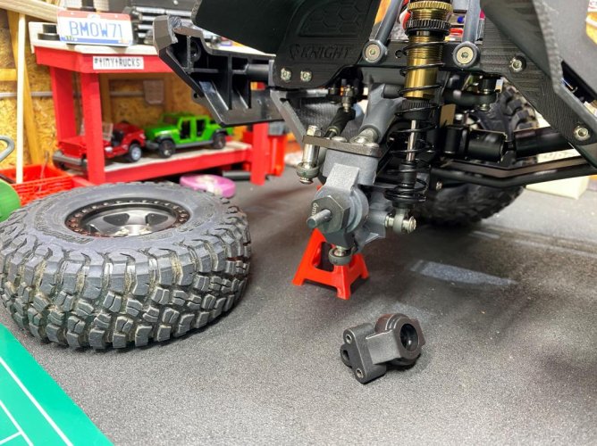
As I was cleaning the workbench up and looking thru the extra pieces that came with the GK Kit that I didn't use, I found a set of hard knuckles for the IFS packed in the bag that held the front hard axle and components.

I decided to go ahead and swap out the "soft" black plastic knuckles for the "hard" gray plastic knuckles since I had them and they match the color of the rest of the plastics on the rig.

IMG_8462 (2).jpg

IMG_8463 (2).jpg


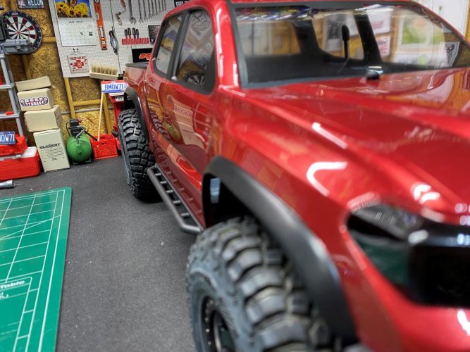
And last night the weather here was finally warm enough to throw some paint on the body. Here is a teaser shot of the Knightrunner "Tacoma" a few minutes after rolling out of the paint shop.:)

More info and pics to come later!

IMG_8482 (2).jpg
 
Back
Top