• Welcome to RCCrawler Forums.

    It looks like you're enjoying RCCrawler's Forums but haven't created an account yet. Why not take a minute to register for your own free account now? As a member you get free access to all of our forums and posts plus the ability to post your own messages, communicate directly with other members, and much more. Register now!

    Already a member? Login at the top of this page to stop seeing this message.

TLT with TTB

That's freakin sweet. Can you take a picture at full compression and fully extended.
The 8" is pretty close on the ranger four wheel drive and 2 wheel drive. The f150 had more because of the the longer arms.
 
most of the flex is comeing from the back it looks like, but it still looks like there is more than 8" of flex up front....i could be wrong

702959_10_full.jpg
 
Not bad, but this one's going to be more of a street truck, so 8 inches will be plenty. Once I get the frame bolted together I'll shoot some flex pics for ya.
 
mandatory flex shot

This is as good as it gets. Any more travel and the dogbone falls out. There's less travel on the driver's side, but I can get some back by notching the aluminum plates under the passenger-side hinge pin.

A little foam from a touring-car bumper will keep the dogbone centered and keep the chatter down.
 

Attachments

  • MVC-032S.JPG
    MVC-032S.JPG
    37.2 KB · Views: 1,333
This is somehting I thought about on more than one occasion cause I wanted to replicate my 1:1 F150 but never even attempted to try it. I am going to have to watch this closely to see how it turns out.
 
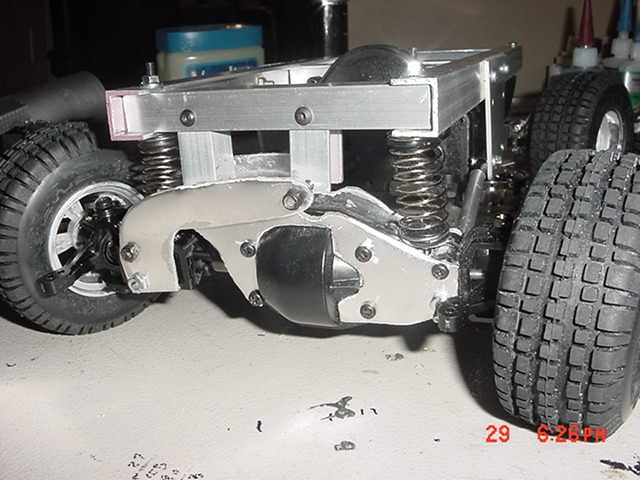
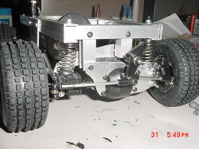
I got some springs on it. Now it sits with the driveshafts about level. Notice the notch for the hingepin above the diff. I'll use limiters in the shocks to keep the dogbones in.

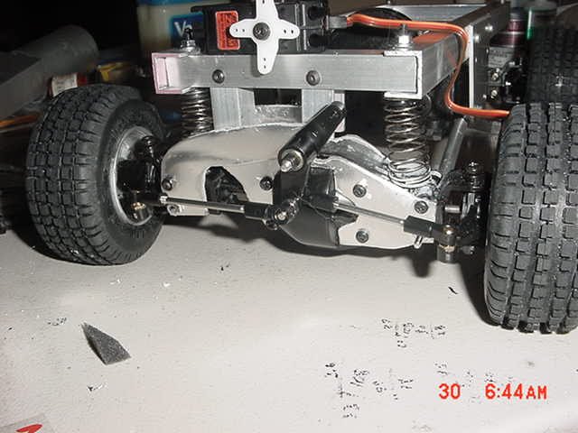
I also got the split steering linkage done, but the camera battery died. I'll post up a pic tomorrow.

Those with particularly sharp eyes will notice that the hingepins aren't drilled straight (the front is lower than the back). This isn't because I'm a hack and do everything by hand; it's because the hingepin has to be parallel to the radius rods, or the suspension binds up.
 

Attachments

  • p9782238.jpg
    p9782238.jpg
    36.6 KB · Views: 1,297
Last edited:
I would like to see more of the A-arm and how you have that set up. I am thinking about building a TIB front suspension (2wd version for the non Ford folk) for my next ranger......
 
Yeah, they had it painted yellow if I remember it correctly.

Here's a pic with the steering links, using a leftover TLT canty.
 

Attachments

  • MVC-032S.JPG
    MVC-032S.JPG
    36.3 KB · Views: 1,265
Last edited:
slugzracing said:
I would like to see more of the A-arm and how you have that set up. I am thinking about building a TIB front suspension (2wd version for the non Ford folk) for my next ranger......

You mean the radius arms? They're just bolted rigid to the axles. I used 4-40 rod sleeved with aluminum tube and ran it through the lower holes in the axle cases. Pretty stone-age, just like the 1:1 :lol:
 
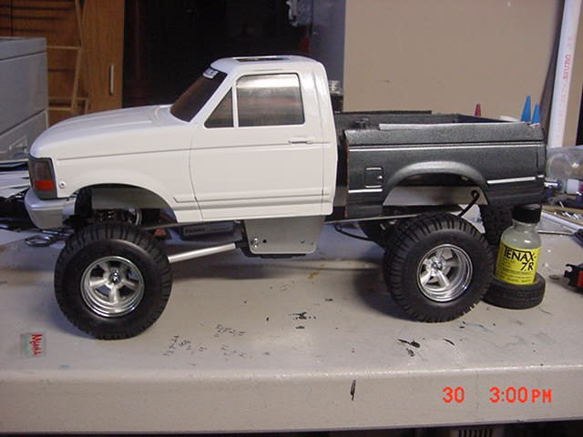
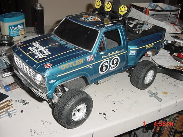
I re-did the wheels today to tuck them into the fenders a little more, added spacers to the radius arms where they meet the chassis plates, and did a mockup using the tow truck's body. The Blackfoot bodies I won on eBay shipped today, so the project is coming along nicely. I also found a speed control that I forgot I had (yes, the Evader has been on the shelf that long), so that's one less thing to buy.

Of course the body in the pic is a King Blackfoot, but the dimensions are close enough that you get a rough idea of what it will look like. The wheels are shown pre-surgery, they're almost 1/4 inch closer to the frame now (each side).

The next phase is to tear it all back apart and make it pretty. I know it looks hack, but I wasn't sure it was even going to work, and didn't want to spend a lot of time on it if I was going to end up throwing the thing in the trash :lol:
 

Attachments

  • p9783448.jpg
    p9783448.jpg
    36.7 KB · Views: 1,208
Last edited:
:shock: :shock: :shock: holy cow man!!!! my dickydo hasnt been this hard in a long time!!!:shock: :shock: :shock: :shock:
 
I think it's time to re-work the passenger side. I'm going to try to tuck the axle beam behind the driver's side, more like the 1:1 TTB. I'll use 1/8 inch aluminum instead of twin .062 plates, so it'll be plenty strong, and look even more scale.

Blazed, too much information :lol:
 
looking very cool Goat, I am not a big ford fan, but props to you on the scale TTB and design ideas.
 
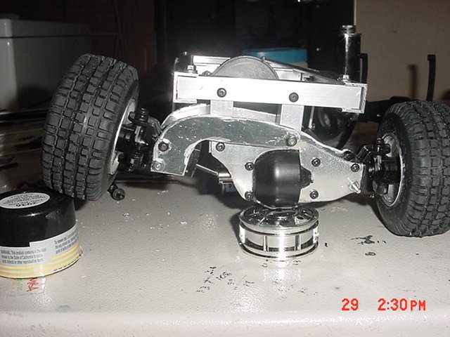
This works better for me. Even though the plastic axle is hanging out, overall the assembly resembles the 1:1 TTB more than it did before, and with the passenger side being 1/8 aluminum (but low-grade flexy stuff made from a salvaged airplane instrument panel) it's stronger than before.

I made the rims from HPI Vintage rims and 8 stock TLT wheels. This is the second go-round on the rims; these have 1/4 inch less offset.
 

Attachments

  • MVC-030S.JPG
    MVC-030S.JPG
    37.8 KB · Views: 1,982
Back
Top