• Welcome to RCCrawler Forums.

    It looks like you're enjoying RCCrawler's Forums but haven't created an account yet. Why not take a minute to register for your own free account now? As a member you get free access to all of our forums and posts plus the ability to post your own messages, communicate directly with other members, and much more. Register now!

    Already a member? Login at the top of this page to stop seeing this message.
  • RCSC

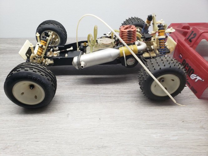
Resurrecting a 25 year old RC10 GT

I'm not yet ready to start on the two bodies that I have for this project but figured why not post up some from +/- 25 yrs ago. I was fortunate enough to find these old photographs in an old box of memorabilia and although I wish I still had some of these bodies, at least I've got some pics. Pretty poor quality but regardless, this thread needs more pics.

Very first RC body I ever did. I wasn't ready to do any graphics but figured a color transition was worth a shot. Black to metallic purple to metallic magenta...


Black to blue with white to flo yellow to green for the flames. Pretty simple but it came out well. I think this was my second body/ first attempt at graphics...


Maybe my forth or fifth body here. I was starting to dig doing graphics...


Kept trying new color combinations/ transitions/ graphics. I liked that there were really no limitations. White with metallic purple to metallic blue for the flames...


White to teal to black and magenta to black with some yellow to give it a little more 'pop'. The 90's really were a lawless time lol...


One of my all time favorites. White to silver and then added red/ blue stripes and white stars. I loved this one...


T-Maxx body...


And another T-Maxx body. Metallic blue to black and then flames were white to silver outlined in royal blue...


Group shot ( although with at least a half dozen missing)...

 
Been having a hell of a time lately, now that I've gotten into fitting all of the electronics. But on the positive side, I'm making changes that although challenging, are really improving overall aesthetics and performance... no shortcuts. I'm very pleased... just wasn't expecting so many little obstacles... and so time-consuming to resolve.

So when I was mocking up the MIP exhaust stinger, I found that it interfered with the rear bumper battery holder. Obvious solution would be to go with the original side exhaust but performance wise I prefer the stinger much more. It has more consistent back-pressure, sounds better, keeps the chassis/ components cleaner since it exits out the back, and just looks more slick. Repositioning the battery wasn't a viable solution either. In order to keep the battery secure, it needed to sit where I initially planned for it to be unless I was going to completely make a new bumper which I wasn't fond of doing for a variety of reasons.

But in order to keep the stinger exhaust, I had to ditch the first version of the cover-plate for the battery holder and fabricate something thinner. You can understand better from pics below. Another issue with the stinger location is not simply that it contacted the thicker cover but also that it hindered access to one of the screw locations for removing the cover and subsequently removing the battery. As you can see, there are four posts that keep the battery in place ( two long/ two short). All four posts also had to be shortened which as simple as it sounds, also presented it's own challenges.

But after a lot of detailed work, the V2 cover is the answer. It's much thinner and utilizes a "slot" on one end and a hole on the other end. It still utilizes two screws but the inaccessible screw now remains stationary ( permanent), utilizing the slot to lock in place and the other screw is the "release" screw that when removed allows the cover to simply slide out and off. Much easier to understand in pics. Version I was 4.23mm plastic. Version II is 2.13mm aluminum. Additionally, all posts were reduced in height by approx 4.5mm. FWIW I was forced to reduce the post heights for battery removal since the location of the stinger doesn't allow the battery to simply be lifted up and out. So the posts had to be shortened in order for the battery to be slightly lifted and then slid out the side.

You can see the difference between the old cover and the new cover here...


Continuing on with the electronics...

Sometimes with a project, you have very little direction initially but then as you progress, you begin to develop and zero in on specifics that are meaningful. At least that's me. All I knew when I started this project was that I wanted to rebuild an old classic.. That was about it. But I soon realized that my goals were to not half-ass any of it, to make things look aesthetically streamlined, and to improve performance anywhere that I could. And also to try to balance the more modern touches with some old-school vibes.

When it came to servos I had a LOT of choices and that became a bit overwhelming until I took a step back. That was when I decided that instead of going with brand new servos, that I would instead take a look at some of my old ones. And what I found was that out of all the servos that I already have on hand, that there was not a damn thing wrong with the two servos that I last used in this rig... a Futaba S9405 and an Airtronics 94737. These aren't great servos compared to what's out there now but, well... they still work and they performed well back in the day.

And at least for now, those are what I'm putting in this one. The S9405 will be for throttle/ brake duties and the 94737 will be in charge of the steering. I may at some point change these out ( or be forced to change them out if one or both happen to fail). But with all the modern touches I've made to this rig, this is one place that I decided to preserve the appearance of the old days.

Along with these old servos I also decided to try to salvage two other old components that again accentuate the retro aesthetic but that are also useful. One is an old MIP temperature gauge and a battery level gauge... no clue as to the brand. The temp gauge was in bad shape so I pulled it all apart and thoroughly cleaned all the contact points, replaced the battery and re-soldered the probe that had somehow gotten sliced in half. It's now working again and seems to be reading accurately. The probe portion wraps around the bottom fins of the engine head and is powered independently via a 357/ 303 button cell. The battery gauge plugs into whatever receiver channel and utilizes a green/ yellow/ red illumination to display the battery life.

Along with the temp and batt gauges, I also had to fabricate a couple of brackets that would look nice and get them situated in plain view. Pics below show what I came up with in terms of the best mounting solution. So we now have the electronics cluster taking shape... throttle/ brake servo ( incl updated linkage), new and modified receiver box/ antenna mount, old temp gauge/ newly fabricated bracket, and old battery gauge/ newly fabricated bracket. Everything is a snug fit but I'm really happy with how it's all coming together.


This is a really cool rebuild!

It made me remember some of what I had in my old RC10GT - a Paris ringed (ribbed for HER pleasure🤣) exhaust and a clear-case Cirrus-branded servo.

Ah, the good ol' days!
 
Thanks, durok! Ron Paris for sure... I remember! By today's "the internet has ruined me" standards... they sure do look, um... multi-purposed lmao.

I've actually got two of the old Cirrus CS-60 clear-case servos. Sadly the mounting tabs are broken on both of em but I thought they were just TOO cool back in the day lol.
 
Back
Top