• Welcome to RCCrawler Forums.

    It looks like you're enjoying RCCrawler's Forums but haven't created an account yet. Why not take a minute to register for your own free account now? As a member you get free access to all of our forums and posts plus the ability to post your own messages, communicate directly with other members, and much more. Register now!

    Already a member? Login at the top of this page to stop seeing this message.

Another 4 Link Thread

now this succeeded in eliminating squat, and maybe it has too much AS now. but i still have more driving to do with it. one thing i liked it that i instantly got performance enhancements for uphills, side hills, side turn to uphill. it kept the back end more planted, and the truck seemed to tool onto its back much less (like a turtle).

Are you sure you increased AS or is it something else that is going on? Remember that an adjustment of one value can mean the adjustment of another.

I would guess that you've actually decreased squat...

this stuff all depends on your setups too. i appreciate that Duuuuuuuuuude is applying this to a "perfect" test environment.

It really does have to be learned in a "sterile" environment. I know what builders of 1:1's shoot for when they set rigs up, but it doesn't do much for us to have the same goals when we have more options available to us. Unless you are building an absolutely perfect 100% scale reproduction of a real rig, how they are set up won't apply.

Its like learning cow biology by studying frogs. The basic principals are still at work in either, but the individual characteristics are different.

my point is that i made one adjustment to just the rear upper chassis mounting points (there are 8 pairs of mounting points, i changed 1), and it made a HUGE difference in how, i perceived, the truck drove. if you try to make 4 adjustments all at once you will never be able to narrow down what made things worse and what made things better.

Tuning is a whole different matter, but the basics are still the same. Make one change, test test test test test, make another change, test test test test test.

Some very seasoned drivers are able to make multiple changes at once, but only because they are already intimately familiar with what those changes mean and how they interact with each other.

sway bars. apologies for the semi thread jack. wanted to get that sway bar point across.

There's nothing wrong with sway bars, other than too many people use them to cover up other issues. The same can be said for springs in general.
 
Last edited:
It really does have to be learned in a "sterile" environment. I know what builders of 1:1's shoot for when they set rigs up, but it doesn't do much for us to have the same goals when we have more options available to us. Unless you are building an absolutely perfect 100% scale reproduction of a real rig, how they are set up won't apply.

Example: I built this buggy a couple years ago with the intent to make is as proportionately identical to its real life counterpart as I could. I had real world chassis dimensions, wheel base, track width, etc to build from. Weight placement was off, but it was a small package and there weren't many choices. If I were to design one from scratch it would have been much different from a suspension standpoint. Links would be longer, different geometry, etc.

qp59w5.jpg


Since we don't have to worry about the same packaging issues that 1:1 builders do (mainly driver comfort and safety) we have more freedom of design which gives us greater tuning options. There are plenty of amputated action figures that will support this theory. ;-)
 
i can't believe it duuuude gave me a headache again!! lots of good information here and lots of stuff to think about, there is a lot of options, thanks guys !!
 
I can see how to figure the values for a link set up like you see on a scaler or a wraith but MOA crawlers can have parallel upper and lower links and then how do you do the geometry for IC, LF, RC, AS/S? I know some crawler chassis have links angled so they intersect at some point in space...but some don't. Any thoughts on that?
 
A very enlightening read here. I had a very basic understanding on Squat / AS, but never knew how it was calculated.. The Wraith diagrams help a lot!

Now if I could only figure out a way to make it easy for me to adjust the suspension geometry on my Wraith.. :mrgreen:
 
I can see how to figure the values for a link set up like you see on a scaler or a wraith but MOA crawlers can have parallel upper and lower links and then how do you do the geometry for IC, LF, RC, AS/S?

I've never owned a MOA, so all I could do would be to speculate and probably be wrong.

I know some crawler chassis have links angled so they intersect at some point in space...but some don't. Any thoughts on that?

Your talking about the uppers?

At some point they will most likely converge, unless they are absolutely parallel to each other.

On a shafty, having the uppers spread out at the axle helps to control torque twist. You have to be careful though...the further they are spread the further out the RC is. If the axle ends are lower than the chassis ends it could result in a really low RC and RA.
 
Thanks for the clarification. I went to bed thinking about suspensions and didn't wake up any smarter. Could be that with MOA the TT on the axle is doing stuff to the chassis in a completely different way than the TT from a driveshaft. Toss in a crazy CG with most of the mass on the front axle and it would be a real trick getting under that with the vectors you sketch out in your OP.

I've had almost no luck getting rid of TT on the Scorpion. Nail the throttle and it lifts one front wheel way up. Ended up putting limiting straps on the shock ends and limiting spacers on the shock rods to keep it from flipping over when turning. Still lifts a wheel. One thing I did notice was having the shocks spread wider on the axle/chassis limited body roll better (duh).

Seems like a candidate for torsion/sway bars. Never messed with that before. Are you going to add any info about those?
 
Could be that with MOA the TT on the axle is doing stuff to the chassis in a completely different way than the TT from a driveshaft.

MOA rigs should not have TT since the entire drivetrain is built into the individual axles.

S/AS is still important.

I've had almost no luck getting rid of TT on the Scorpion. Nail the throttle and it lifts one front wheel way up. Ended up putting limiting straps on the shock ends and limiting spacers on the shock rods to keep it from flipping over when turning. Still lifts a wheel. One thing I did notice was having the shocks spread wider on the axle/chassis limited body roll better (duh). Seems like a candidate for torsion/sway bars. Never messed with that before. Are you going to add any info about those?

Sway bars should be the last thing you consider. Most of the TT can be tuned out through geometry and UD/OD gears.
 
I gotta admit, I'm still a bit overwhelmed by all this. But I did finally learn how to draw those neat little lines on there! :ror:
Feel free to offer any input you feel would be pertinent to the thread.
(resized the pics a little large, but still within the 800x1200 upload limits)


-----------------------------------------------------------------------------
First up, front suspension.
Red indicates where the links are currently positioned.
Thin green lines indicate alternate mount points for the upper links.

trubble-48139-albums3743-54278.jpg


Don't really have much of an option on the lowers, but shall I assume the thin green lines are really not my friends?
-------------------------------------------------------------------------------
Next, rear suspension.
Red indicates where the links currently are.
Thin green lines are alternate mount points for the uppers.
Thin blue line is where the lowers would be had I played by the rules and put them where they're supposed to be. :flipoff:

trubble-48139-albums3743-54279.jpg


Should I assume that I would be better off on the thin blue line?
Are the thin green lines still not where I wanna be?
----------------------------------------------------------------------------------
Thanks for your input.
 
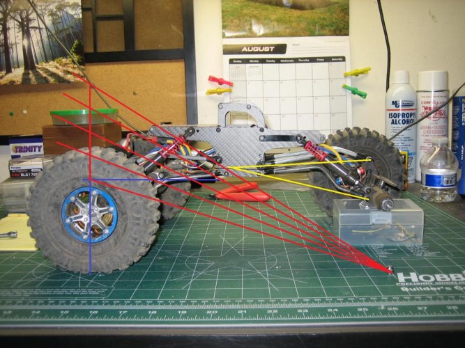
And remember its ready to run weight. Don't for get to lock the suspension in place at ride height when figuring out cog, otherwise the geometry is inaccurate.
 
I made this chassis and got it on the rocks yesterday. I made a couple of adjustments, so I did the whole antisquat pic. Assuming my CG is in the right spot can this be correct? 200%+ antisquat :shock: Has anyone else done this with a pro rig?
 

Attachments

  • Antisquat.jpg
    Antisquat.jpg
    175.5 KB · Views: 889
Okay, tried another (fully assembled) rig.

Is there something i did wrong here? Is the CoG actually at or below the skid?
Doesn't seem right that a shafty with an aluminum chassis, trans, and motor above the skid should hang like this.
The wheels are aluminum, but otherwise unweighted.
The rear axle is hung by the lower shock mounts, and the front axle is hung by the c-hubs.
Was that not right? Should I have hung it by the upper shock mounting points instead?

trubble-48139-albums3046-54429.jpg


trubble-48139-albums3046-54428.jpg


trubble-48139-albums3046-54427.jpg


(headscratch)

.
 
Could be right, could be not right. I like to hang it off of the chassis so that there is a greater angle where the two lines intersect. It makes it easier to pin point the cog.
 
Back
Top