• Welcome to RCCrawler Forums.

    It looks like you're enjoying RCCrawler's Forums but haven't created an account yet. Why not take a minute to register for your own free account now? As a member you get free access to all of our forums and posts plus the ability to post your own messages, communicate directly with other members, and much more. Register now!

    Already a member? Login at the top of this page to stop seeing this message.

Shop Holmes

Mach3. I can't figure out how to get hsm working proper yet, but I only spent 5 minutes on it. The one problem is that not all of my drawings in CAD are oriented properly for machining, so I have to export them and import them to flip em unless there is a special feature I am missing in sW10

Insert reference geometry, wcs. Then use the wcs when you create your job in hsm
 
I have been trying to get HSM works to output some NC or TAP files that Mach 3 can use, but so far they all have some sort of error. Zero radius arcs, invalid codes, etc.. Any post processors that are known to work with mach3? I'm using the Mach2 one that is included in HSM but it won't work with pockets.

It does output a lot nicer code though. The only issue I'm really having besides the random errors is the conversion from metric drawings to run english on my machine. Everything but the lead in helix seems to be fine, but the lead in is huge.

Not sure what the issues are. Does mach3 use standardized (RS274/NGC - "fanuc") code? if so, my work post processor would probably work just fine, perhaps with some small modifications.. Perhaps post up a sample of some code you would feel comfortable running on your machine, i'll see how similar it is.
 
Found out that I needed to change Mach3 to Incremental mode to get rid of the errors. All good now!

Haven't done much but production work on the mill lately. I did get a chance to cut up some extra armature holders though. Needed more racks to hold them between work stations!
 

Attachments

  • armature trays.JPG
    armature trays.JPG
    147.1 KB · Views: 1,263
With opening an Ebike storefront lately I haven't had a ton of chances to play on my machinery. I need to move the CNC to work now, I'm not interested in working from home at all since my shop is just a few miles away. Working two places in a day is not very effective for me.

But, I did get totally sick of the resin impregnation process when we make stators and rotors. So I built up that resin chamber I was talking about in post two. Within the first batch of armatures I had already saved time on production. In four more weeks the effort and materials to build the chamber will be covered as well. The chamber was built three weeks ago, I am just now getting time to post it up.
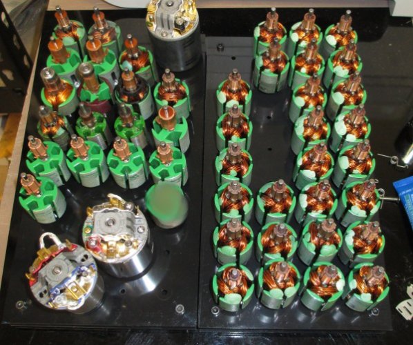
A recap:
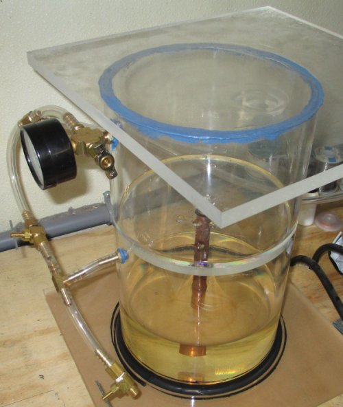
The second project I am working on is a Vacuum chamber for resin impregnation. No deadline on this, as we already have a dipping chamber in use. This chamber will primarily be used for 540 brushed armature work, as we have another chamber that is used for ESC impregnation and molding work. I'm a bit lazy when it comes to manual work, so when I can build a machine to work smarter instead of harder you bet I will do it!

This will technically be a VOI (vacuum only impregnation) process chamber, since VPI (vacuum pressure impregnation) also uses positive pressures and machines in the 10s of thousands of $$ range. I got chewed out by a resin rep one day about the difference of VPI and VOI . The resin we use for impregnation calls for vacuum on wire bundles thicker than 1", wire sizes smaller than 30ga, or stators where resin cannot penetrate along the longitudinal direction. Since a normal 540 armature does not meet any of these criteria, the vacuum duration and intensity is non critical. This device will use vacuum for automation, but a change in the routine could easily make it a VOI system for parts that do need vacuum for proper impregnation. I may automate the chamber with PLC, but I don't think it will be needed.


A quick rundown of how I built it. The top, middle platform, and bottom are 1/2 inch plexy, square foot. The chamber is made of 8" plexy, I think it was just a hair under 1/2" thick. I first tried drilling and tapping to install the bottom, but it was not a good process because of the wall thickness. The bit would wander and deform the walls since plexy is kinda melty. A stub drill and faster pecks would have worked better.

Instead of mechanical fastening, I decided on chemical instead. A good soak in acetone joined the bottom to an almost airtight seal, I didn't finish the tube well enough for a perfect seal. Doing it again, I would have lapped the tube on sandpaper to get it perfectly flat. The middle platform also got the acetone treatment, and made a perfect seal. To fix the bottom side seal I used black RTV around the base and pulled a vacuum on the system to bring it into the cracks. Worked perfect!

The top seal was made with blue gasket maker. I roughed up top surface of the tube and applied a generous portion of gasket maker. Then I ran over the silicon with a concave forming tool, and set the top lid down with some Vaseline as release agent. After a short cure the top was removed and the gasket allowed to fully dry. It was pretty easy.


The rest of the chamber is simply hoses, fittings, a vac gauge, and valves. I can bias the pressure between top and bottom chambers to move resin up or down. It is pretty simple to operate. Just add a bit of air to the lower chamber to push resin up, then balance the pressures or turn off the vacuum to stop the flow.


A typical resin process for my needs calls for a 60 second dip at a specified temperature at zero inches mercury (regular atmosphere). Over the last 9,000 armatures we haven't had a single resin related failure, so the resin manufacturers' instructions are sound "thumbsup". During operation of my resin chamber I let the armatures sit for 60 to 300 seconds depending on how the resin is flowing, followed by a drain period per the instruction sheet for the particular resin. Remove, clean, and bake 8)

Instead of handling 20 to 40 armatures one at a time, we can now do ONE process that takes minutes. Hello free time to do other things in life, like searching for better prices on penny whistles and candy necklaces. :mrgreen:


Next I will trim the top on my bandsaw to make the machine a bit more svelt, install a bung when it is needed, add in a few more valves for easier pressure control, and start testing PLC items to fully automate it. My biggest concern is the proximity sensor needed for automation. I think a capacitive type should work on the resin, but I don't have one here to test.


As you can see it gets dirty QUICK! The resin is super nasty and doesn't really clean off the plexy fully without getting solvents involved.
 

Attachments

  • Resin Chamber.JPG
    Resin Chamber.JPG
    128.5 KB · Views: 1,073
Next I will trim the top on my bandsaw to make the machine a bit more svelt, install a bung when it is needed, add in a few more valves for easier pressure control, and start testing PLC items to fully automate it.

Use a router w/ a straight cut bit that has a roller bearing on the tip- fast clean cut."thumbsup"
 
Thats a great idea for a better finish! I don't have a router, but I can probably find one. I wonder how good my freehand router skills are compared to a band saw.
 
Use a router w/ a straight cut bit that has a roller bearing on the tip- fast clean cut."thumbsup"

Thats a great idea for a better finish! I don't have a router, but I can probably find one. I wonder how good my freehand router skills are compared to a band saw.
The roller bearing allows you to run the bit around the tube as a guide, no "free-hand" involved.;-)
 
I see, so as long as the top is secured it will just make it nice and neat. A good vacuum would be enough to keep the top on. I like it!
 
We resistance braze all brushed motor armatures and normally don't need anything more powerful than 1000w. I had a project that required more heat than our regular equipment could handle though, so I started a new machine last month in my spare time. Just got it finished up today and used it for the first time, works exactly as planned "thumbsup"


On this new machine the primary transformer is a simple 220v 60hz transformer, vs our other machine that is 120v. This allows for a lot more power without worrying about tripping the breakers. We tap different points for different output settings, plenty of adjustments for any work. To bump the output where we need, a secondary transformer is used.

I sourced a new transformer for the secondary from my scrap heap. I had killed a MIG welder a few years back and didn't throw it out. The secondary coil became the primary coil, and I used 3 parallel 2 ga welding cables to wind up a new secondary for a 10:1 ratio. If you do the math on the continuous rating for that much wire, you can get an idea on the current we are dealing with.


Spent an hour using it today, and it works as planned. The final coil is rated to handle the regular current continuously, but duty cycle doesn't go past 25% so there is room to double the heat if needed. Not needed, but nice to have the overhead. 8) After the hour of use the transformer body was still at room temp, and the wires leading from the coil were 85f because of heat wicking from the tool head.


Glad to get that out of the way, on to the next project!
 

Attachments

  • Origional Transformer.JPG
    Origional Transformer.JPG
    120.8 KB · Views: 966
  • Chopped one.JPG
    Chopped one.JPG
    113.2 KB · Views: 972
  • Chopped 2.JPG
    Chopped 2.JPG
    170.2 KB · Views: 943
  • Chopped 3.JPG
    Chopped 3.JPG
    170.6 KB · Views: 926
  • All apart.JPG
    All apart.JPG
    119.4 KB · Views: 944
  • Fitting the wire.JPG
    Fitting the wire.JPG
    108.6 KB · Views: 951
  • Resistance Brazer secondary installed.jpg
    Resistance Brazer secondary installed.jpg
    71.1 KB · Views: 934
Man I want tools just to make tools and fixtures. Seems like all the machinists have more fun making things they will use to make parts than making the parts.

Lots of awesome stuff in this thread John.
 
This job needed an angle grinder and screwdriver to pull apart the transformer. A clamp and welder put it back together. The terminals were gooped up with contact grease and pressed in a vice. Pretty simple tools, just took a bit of time and math to execute properly. Making it was fun, but the satisfaction when it was completed had me floating around the shop! To put it into perspective, a modern variable machine capable of 1500 amps would cost between 8 and 15 grand! This one tops out at 2600 amps.

I have parts for a long throw automated head, one day ill get to it when the travel is needed.

Up next is a high torque winder and an attatchment to install a lathe headstock on the mill.
 
Some shop updates.


The new resistance brazer is working very well. So well, my other machine isn't getting used but for some basic resistance heating work. I completed it just in the nick of time evidently, no more than a few days afterwards my original machine lost gusto and the max temp started falling steadily. Now I get a chance to scrap the old machine for parts :twisted: more on this down the road when I get some time to tear it down.


Projects on the front burner for my shop:

Control resin chamber temp with better accuracy
Automate and rebuild the thermoset oven (powdercoat and rotor oven)
Automate and refine the resistance brazer

An order for proportional–integral–derivative controllers (PID controller) was made from Auger Instruments. I picked up a slew of sensors and PID controllers, along with plenty of solid state relays. Got one relay for the resin heater, one relay for the oven, and one 100a 400v relay for the resistance brazer.


First up, the resin chamber gets a fancy new K sensor and PID. Drill a hole, make an enclosure, plug it in. Pretty straight forwards.


Next up is the resistance brazer. It needs a solid state controller so we aren't installing new contactors every few months. The primary transformer controller I am using is not intended to be switched off under load . A SSR is getting installed into it and tied into the control board. Then we will reassess the kickback voltage and begin work on a new braze head controller. It will employ PLC for the head automation. I am considering just programming my own chipset to reduce costs, off the shelf PLC controllers are not cheap and don't offer me any advantages besides a simplified language set.


Third project is the thermoset oven. The one I have now works just fine, but while I was ordering goodies for the other machines I went ahead and got automation controls for an oven too. Right now we just turn the oven on and set a timer, which is a real bummer when the oven starts late in the day and I have to come to the shop at 10pm to shut things down. There are spare ports in the security camera system so we will install a camera on the oven for off site monitoring of all specs.


I also have a side project of building a kiln for my mother in law. I'm only getting a parts list together, others are doing the assembly. There are some pretty cool PID controllers specifically for such purposes, I was looking for kiln controllers originally and decided to automate my equipment first :lmao:. Totalled it up, and they will spend between 600 and $800 in parts for a kiln that retails at $5000. There is surprisingly little information about doing this yourself, but it isn't any different than building a heat treat or tempering oven.
 
Back
Top