• Welcome to RCCrawler Forums.

    It looks like you're enjoying RCCrawler's Forums but haven't created an account yet. Why not take a minute to register for your own free account now? As a member you get free access to all of our forums and posts plus the ability to post your own messages, communicate directly with other members, and much more. Register now!

    Already a member? Login at the top of this page to stop seeing this message.

Steve's VS410 Phoenix Build II

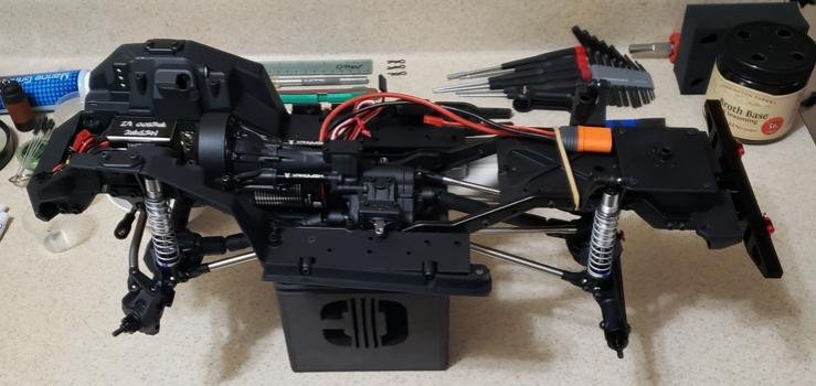
Looking good! I'm right behind you, have the first couple of steps done on the trans. Are you using a metal motor plate and stand offs? I'm just using the stock ones, I hope that it's all stiff enough to not move around too much when installed in the truck. This is way more complicated than any tranny I've built before. :shock:

No worries with the stock plastic motor mount plate n standoffs. I built my first phoenix in a gspeed v3 chassis n run it on 4s all the time. It even took a 60 ft tumble off a cliffside n still runs perfect. Ive got a build thread in the 1.9 section i think... May be here in the VP section too, i dont remember lol
 
Steve, shes comin along nicely brother! I had the same problem buildin my straight axle. Didnt realize that standoff screwed into one side of the bearing plate. Ive got mine built n a buddy painted the chevy stepside body for me. Unfortunantly, i havent got to run it yet. Had issues with the esc, which was dissappointing. But i had my trusty v3 phoenix with me, shes never let me down lol
 
Steve, shes comin along nicely brother! I had the same problem buildin my straight axle. Didnt realize that standoff screwed into one side of the bearing plate. Ive got mine built n a buddy painted the chevy stepside body for me. Unfortunantly, i havent got to run it yet. Had issues with the esc, which was dissappointing. But i had my trusty v3 phoenix with me, shes never let me down lol

Thanks, I've been told the standoff is only used in the VFD tranny, it's not long enough anyway for the twin and hits the gear anyway too. I hope you get your ESC problems fixed more bucks for a new one. And glad to hear you were able to keep rolling. "thumbsup"
 
I ran into something different building the tranny. I was at the point of building the tranny in the photo and looked over at the parts I had left. I saw a small shaft that resembled the idler shaft but with threaded ends. I couldn't figure it out at first, I watched vids on building both the VFD and the VFD twin. I noticed the plastic bearing plates had a standoff two piece half on each one. I looked at my bearing plates and there was no standoff, I then realized that they were aluminum and that small shaft was the standoff. Originally I was going to ask what it was, but now my question is did I get lucky or does the aluminum bearing plate kit come with the straight axle kit. The idler shaft is next to it in the photo. And my last question is before I go over to see if I have to back up is at what point and how do I install it.

Did you end up installing this? I just finished my trans and noticed that part but didn't see anything in the manual about it, or even in Harley's video.

Edit, nevermind, I just read your reply to Indybama above.

No worries with the stock plastic motor mount plate n standoffs. I built my first phoenix in a gspeed v3 chassis n run it on 4s all the time. It even took a 60 ft tumble off a cliffside n still runs perfect. Ive got a build thread in the 1.9 section i think... May be here in the VP section too, i dont remember lol

Thanks for that info! Should be good then, lol.
 
Last edited:
Here's the pics of the balance port adapter.

Thanks again, again and here too again. I ordered the 2s and 3s.

Edit, nevermind, I just read your reply to Indybama above.

Yea, the way I post is like a diary. I sorta talk too much, but if I run into something new or have a problem I will post it in order to help others. So if you read my thread's carefully you should catch most problems or tips. I also built the Phoenix portal the thread is "Steve's VS410 Phoenix Build" it maybe of help too. BLUJEEP you should start your own thread, new points of view and new photos are always welcome.
 
Last edited:
Thanks! I'll read more thoroughly before posting, lol. I have a couple of issues on mine, will start another thread for that.
 
I researched more about using the balance port to power my direct power servo and Holmes Hobbies did not recommend this for their SHV650 16v direct power servo. I then e-mailed NSDRC and asked them, this is their reply. "Thank you for contacting us! To start, we do not recommend using the balance ports for powering servos or winches. Balance ports are not made for drawing power and are limited on the amount of current they can flow. We recommend you use a solder connection or one of our plug and play In-Line adapters." So I'm going to unsolder the XT60 plug on my Fusion Pro and put a IC5 on it so I can plug into my battery IC5 and wire in a RCY JST plug into it for my direct power servo.
 
So I'm going to unsolder the XT60 plug on my Fusion Pro and put a IC5 on it so I can plug into my battery IC5 and wire in a RCY JST plug into it for my direct power servo.

That is exactly what I would do. While your at it add a second JST for lights!

The balance port connector is not what I normally run, but have used them for testing before I soldered the JST in.
 
Finished the wiring. But now I'm thinking this servo might be to powerful for plastic axles. I might get a different servo and use the RS800 servo on my flatbed with the Currie VS4-10 D44 axles. That way I can use the JST connection for the lights.
 

Attachments

  • Screenshot 2023-03-14 183258.jpg
    Screenshot 2023-03-14 183258.jpg
    77.8 KB · Views: 427
Been busy but managed to get half the driveshafts built and installed on the motor/tranny. Waiting for my shock tool to arrive before I start shocks and links. Made my own (no pic) tool for the link ends. I also modified a TRX-4 rear bumper for my Phoenix. I think it will miss the tyres if not I'll extend it.
 

Attachments

  • Screenshot 2023-02-05 094350.jpg
    Screenshot 2023-02-05 094350.jpg
    17 KB · Views: 421
  • Screenshot 2023-03-17 175556.jpg
    Screenshot 2023-03-17 175556.jpg
    40.4 KB · Views: 415
  • Screenshot 2023-03-17 175723.jpg
    Screenshot 2023-03-17 175723.jpg
    27.5 KB · Views: 416
Yes I'm using the stock body. All I had to do was use my 1x30 belt sander and round the square mounts, it fits nice and tight. I am in the process of modifying the stock bumper to fit in between the bumper and chassis. So that I have the tabs (holes) for the rear body posts. If that doesn't work and it will, I would manufacture angled L brackets from Kydex and attach to the rear rx (fuel cell) box. All that is left for me to do is sand the bumper down a little and maybe open the holes for the mount a little more. It already fits nicely but I want to have the bumper as tight as I can to the chassis. To make the holes in the bumper, I used a hacksaw to cut the two mounting post off flush with the inside bumper opening. Then I marked and made a starting hole with my x-acto knife (broke my tip) :cry: 
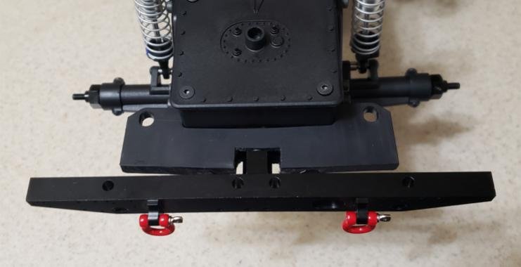
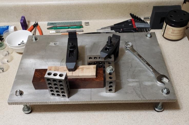
Then I used my drill press starting with a small dia. bit and drilled through the mounting post. I used bigger bits till I got to 1/4" and then I used a round file to finish it up.
 

Attachments

  • Screenshot 2023-03-18 111954.jpg
    Screenshot 2023-03-18 111954.jpg
    33 KB · Views: 383
Last edited:
Looking good! I think I have a simlar version to that bumper, but for a 10iii. It comes with the round mounts and I test fitted it to the Phoenix no problems. Still admire the custom efforts going on "thumbsup"
 
Looking good! I think I have a simlar version to that bumper, but for a 10iii. It comes with the round mounts and I test fitted it to the Phoenix no problems. Still admire the custom efforts going on "thumbsup"

Thanks. Finished the rear bumper conversion. Installed the axles, shocks, sliders and fenders.
 

Attachments

  • Screenshot 2023-03-21 185706.jpg
    Screenshot 2023-03-21 185706.jpg
    41.3 KB · Views: 362
  • Screenshot 2023-03-21 185453.jpg
    Screenshot 2023-03-21 185453.jpg
    25.9 KB · Views: 348
Ordered some nice wheels and hubs from Gmade. I've also decided to paint my body dessert sand. Like my old jeep cherokee. I have a question too, why does the portal have 5mm wheel locknuts and the straight axle 4mm?
 

Attachments

  • Screenshot 2023-03-21 231045.jpg
    Screenshot 2023-03-21 231045.jpg
    27.5 KB · Views: 343
  • Screenshot 2023-03-21 231124.jpg
    Screenshot 2023-03-21 231124.jpg
    22.7 KB · Views: 340
Those will look good! I have some GMade SR-04's on my Cherokee. They're nice and heavy.
 
Put the radiator and battery tray in so before I start the body, I need a place for my Rx. I've decided to put it up front next to the steering servo. I put the Rx in my black portal on the skid so no creek splashing for it. I want my straight axle to be able to tackle shallow water. I'm building my own Rx box for up front. First I made a base plate out of HOLSTEX™ Carbon Fiber/Tactical thermoplastic 0.080" for the servo tray. I also setup my small jig table for tomorrow, when I start on the Rx box. I have a block of maple burl that I'm gong to use as a molding form. Discounting the length I'm just using one end, the dimensions are 1.24"x2.035". Which will be the inside dimensions of the Rx box, the height including the base plate will be 1.5". I have never used thermoplastic before and am interested in seeing how it does at forming 90 degree bends. Later today I'll form the bottom and two sides from one piece and go from there. If that goes well I might form the top and the two remaining sides the same way by turning the bock on it's side and adding .160 or more to overlap the ends of the previous formed bottom and sides. Then I'll cut out the hole for the top, leaving material at the corners for screw holes. I've also made four dowels from the parts tree, which I will glue into the corners for the screws. I probably could leave out the dowels and go with bigger screws if and when the holes became deformed, but that VP plastic material is pretty tough and I don't know how tough that thermoplastic is.
 

Attachments

  • Screenshot 2023-03-26 023644.jpg
    Screenshot 2023-03-26 023644.jpg
    41.6 KB · Views: 293
  • Screenshot 2023-03-26 023757.jpg
    Screenshot 2023-03-26 023757.jpg
    62.3 KB · Views: 289
  • Screenshot 2023-03-26 024010.jpg
    Screenshot 2023-03-26 024010.jpg
    50 KB · Views: 282
The forming of the Rx box didn't work as good as I thought it would. The material cools down too fast, especially when the material makes contact with 123 blocks. However I was able to get the bottom and two sides formed after a few tries, but no square 90 degree bend. I used epoxy and glued the sides on. Not finished yet, should be finished tomorrow. I did find some rubber for my wheels.
 

Attachments

  • Screenshot 2023-03-28 233357.png
    Screenshot 2023-03-28 233357.png
    153.7 KB · Views: 259
Rx box finished. I'll put shrink wrap on the grommet and wires when I install the Rx, I only have 30mm and 40mm shrink wrap right now.
 

Attachments

  • Screenshot 2023-03-29 185547.jpg
    Screenshot 2023-03-29 185547.jpg
    38.2 KB · Views: 238
Back
Top