• Welcome to RCCrawler Forums.

    It looks like you're enjoying RCCrawler's Forums but haven't created an account yet. Why not take a minute to register for your own free account now? As a member you get free access to all of our forums and posts plus the ability to post your own messages, communicate directly with other members, and much more. Register now!

    Already a member? Login at the top of this page to stop seeing this message.

supercooper's RedCat Super Mods (aka how to make an RC Super almost acceptable)

Version 3.0:
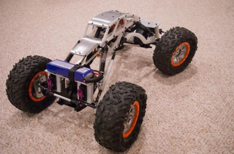
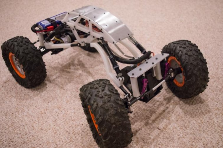
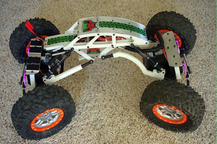
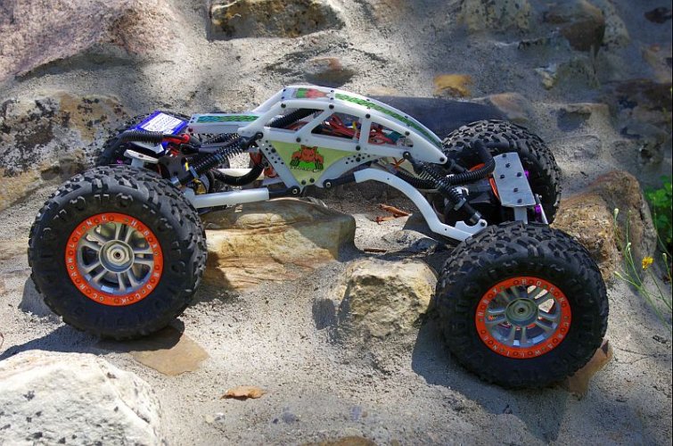
This was a major redesign - I decided to build a bodiless wedge-style chassis with high clearance rear links, inspired by the French Dahu, but using a more conventional shock and spring suspension instead of a torsion design.

I modeled the chassis parts in Google Sketchup, printed the plans out on legal paper, sprayed the back of the paper with 3M contact adhesive, let it dry for about 5 min, and then applied the paper pattern to some ultra high density polyethylene (UHDPE) 1/8" sheet stock I had on hand. I cut out the left and right hand parts at the same time by screwing two sheets together with 3mm machine screws using hoes from the pattern. This approach worked like a champ and it only took me a couple of hours to make all four chassis pieces.

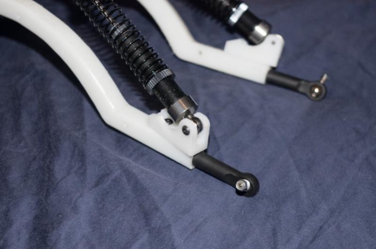
The links are made out of 1/2" UHDPE with the curved rear lower links were made using the same approach as the chassis pieces (the front lowers are just straight pieces). For the ball ends I used 4 sets of upper ball link ends from the original RC Super Rockslide attached with 6mm bolts.

I reversed the shocks to lower the COG and made link mounts out of 1/2" UHDPE.

I also used two rock rollers on the bottom of the chassis, one each on 1/4" standoffs used as both axles for the rollers and mounts for the lower links. The rollers are made from a series of UHDPE disks to minimize friction when high centered on uneven rocks.
 

Attachments

  • Version_3.jpg
    Version_3.jpg
    45.8 KB · Views: 1,652
  • Version_3-8.jpg
    Version_3-8.jpg
    43.8 KB · Views: 1,400
  • Version_3-4.jpg
    Version_3-4.jpg
    43 KB · Views: 1,383
Last edited:
I used two Turnigy 1501 servos linked together. The servo mounts are made from 1/2" UHDPE bolted to the upper AU bracket. I had to mount them vertically to have enough clearance between the transmisison cover and the lower link mounts. This was a compromise between added torque and a slightly higher COG. I also trimmed the outer driveshaft dogbone cups shorter by about 0.1" to increase the steering angle. This necessitatted longer servo arms, as well, so the steering is completely redesigned. Tons of torque now with decent steering angle.

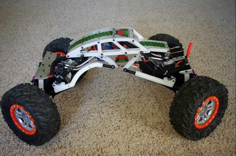
The skins are made from AU flashing. I think they look pretty cool.
 

Attachments

  • Version_3-11.jpg
    Version_3-11.jpg
    68.8 KB · Views: 1,463
  • Version_3-12.jpg
    Version_3-12.jpg
    64.7 KB · Views: 1,475
Last edited:
I decided to name verion 3.0 FrankenCat and made decals based on a modified version of the RedCat Racing logo.

I also narrowed the wheels by 7/8". This recesses the beadlock rings and lets the sidewalls get more grip. It also gave me about 1/2" more clearance with the lower links (they were rubbing with the new steering mods).
 

Attachments

  • Version 3 with Skins 03.jpg
    Version 3 with Skins 03.jpg
    118.5 KB · Views: 1,530
  • Version 3 with Skins 02.jpg
    Version 3 with Skins 02.jpg
    159.9 KB · Views: 1,604
  • Version 3 with Skins 01.jpg
    Version 3 with Skins 01.jpg
    136.2 KB · Views: 1,488
Last edited:
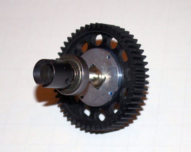
First major failure: the final drive gear in the transmission rounded out the flats that keep it from slipping on the drive shaft. I fixed this by making reinforcing plates out of some left over 1/8" AU flat stock. I turned the stock on my mini lathe to the right diameter and then filed the flats by hand, checking the fit often to ensure I didn't make the rectangular hole oversized. It looks like RedCat engineers had anticipated this because there are four holes for flathead screws molded into the ring around the center of the gear, but no reinforcing plate was installed. I used four small 1/4" sheet metal screws to attach the HM reinforcement plate to the gear using these pre-made holes.

You can see the damaged gear on the upper right, the reinforced replacement gear on the upper left, the reinforcement plate on the lower right, and the drive shaft on the lower left in the picture below.
 

Attachments

  • Diff Gear mod 01.jpg
    Diff Gear mod 01.jpg
    74.7 KB · Views: 1,382
Last edited:
Here are pictures of both sides of the finished reinforced final drive gear and drive shaft assembled before installing back into the transmission.
 

Attachments

  • Diff Gear mod 02.jpg
    Diff Gear mod 02.jpg
    50.9 KB · Views: 1,380
  • Diff Gear mod 03.jpg
    Diff Gear mod 03.jpg
    56.6 KB · Views: 1,350
Thanks ekd! I'm a fan of your real machinist and mechanical engineeirng expertise, as I'm just a hack. But I think we both share the philosophy of enjoying the journey and learning something new along the way.
 
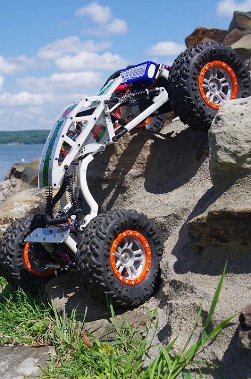
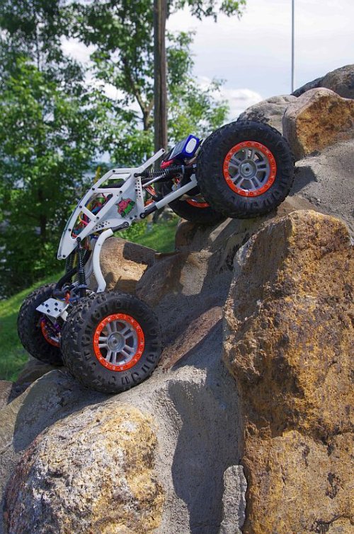
Here are some pics of FrankenCat on the rocks. First serious test run on "Mt Herman" while on vacation at the Chautauqua Institute in NY. I'm pretty happy with the performance, but it still needs a little more suspension tuning (too much flex) and I need to add some knuckle weights to the rear wheels.
 

Attachments

  • On_the_Rocks01.jpg
    On_the_Rocks01.jpg
    126.8 KB · Views: 1,367
  • On_the_Rocks03.jpg
    On_the_Rocks03.jpg
    142.4 KB · Views: 1,312
Last edited:
Thanks ekd! I'm a fan of your real machinist and mechanical engineeirng expertise, as I'm just a hack. But I think we both share the philosophy of enjoying the journey and learning something new along the way.
I just wish I knew half of what you do about manipulating the flow of electrons.

Yup. The day someone comes out with the ultimate crawler, at a fair price... I'm getting a boat.

Here are some pics of FrankenCat on the rocks. First serious test run on "Mt Herman" while on vacation at the Chautauqua Institute in NY. I'm pretty happy with the performance, but it still needs a little more suspension tuning (too much flex) and I need to add some knuckle weights to the rear wheels.
OMG!! I'm blind!

:mrgreen:
 
'Sorry, for some reason I couldn't successfully post all three pictures at once, but the first two are now up. And the third is posted here.
 

Attachments

  • On_the_Rocks02.jpg
    On_the_Rocks02.jpg
    137.2 KB · Views: 3,035
Hi there.
I would just like to thank you for creating this build thread.
I just bought one yesterday, well the HBX one,and was looking for some great ideas for good mods, and this is how I discovered your thread.

Thanx
Charel
 
Hi, I also have a HBX Basilisk in modifications, but your this spectacular, in Portugal there is no great ease in finding parts for 1/8 scale, I'm doing my own chassis, but has not yet found links like those that have in your HBX.
 
spayz, the link ends are from the Super Rockslide front/rear upper links, see Red Cat Racing replacement part number RCL-P019 (throw away the "Y" part). You will need four of these to get 8 link ends. I tapped them for an M6-1.0 thread and used a hex bolt screwed in half depth and then cut the hex head off and screwed on the link. You will also need 1 package of 8 ball screws, Red Cat part number RCL-H004. Good luck with your build!
 
I did my links with 8mm aluminum rod, but have yet to find a way to fix the shocks on the links.
 
Back
Top