JP98_
Newbie
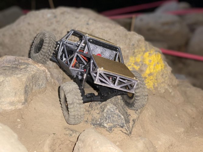
So after my recent Jeep LJ builders kit endeavor I decided to of course test my CAD capabilities again with the wild hair of designing an IFS kit for the SCX24... again cause why not:lmao:
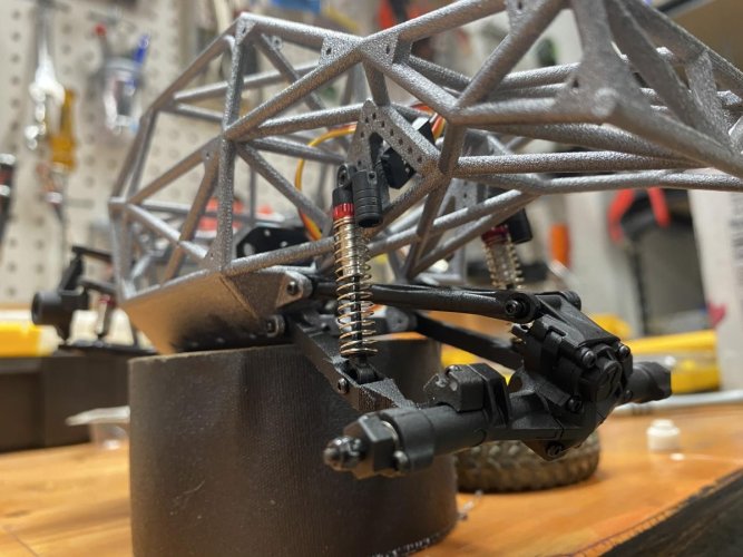
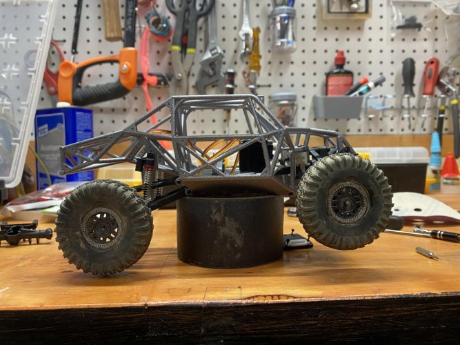
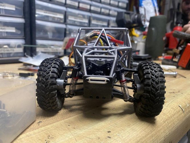
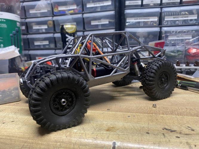
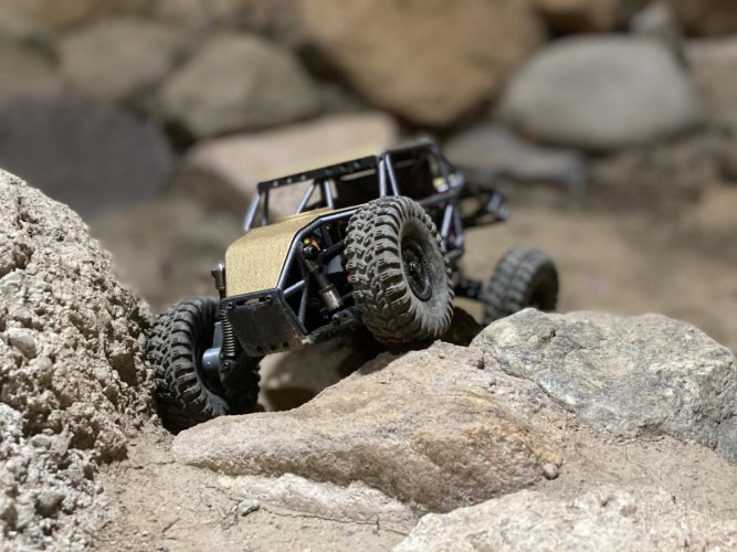
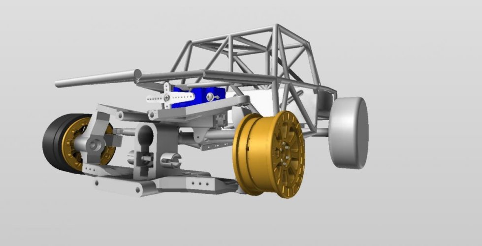
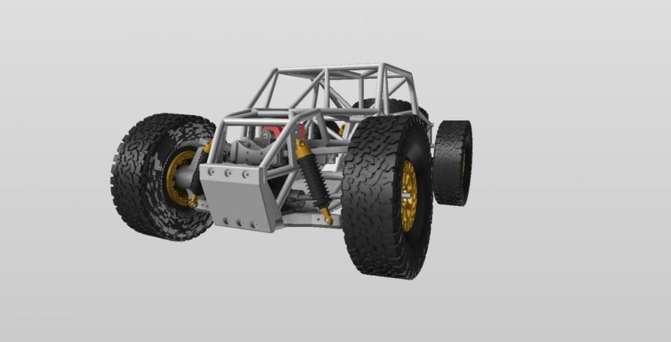
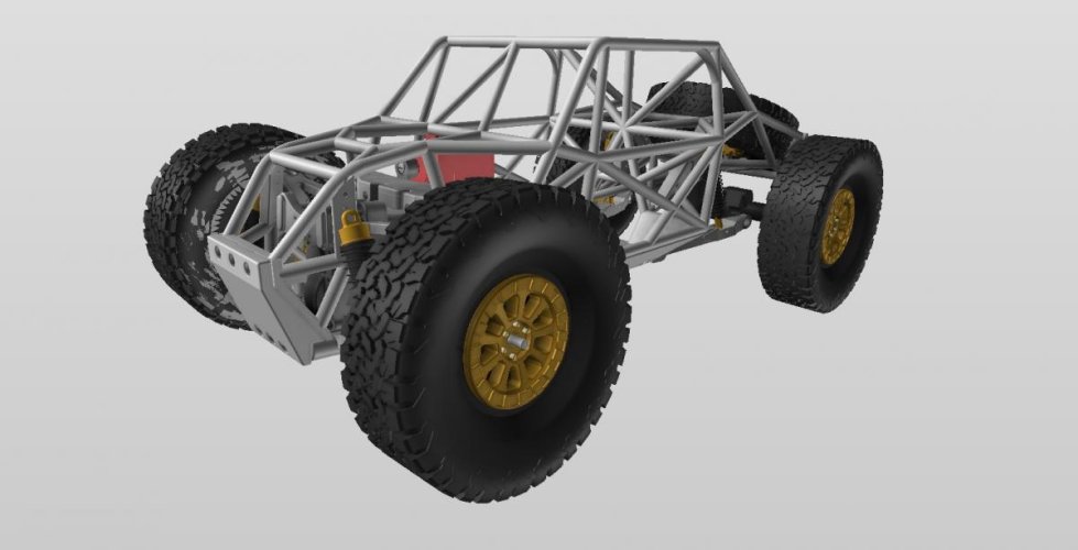
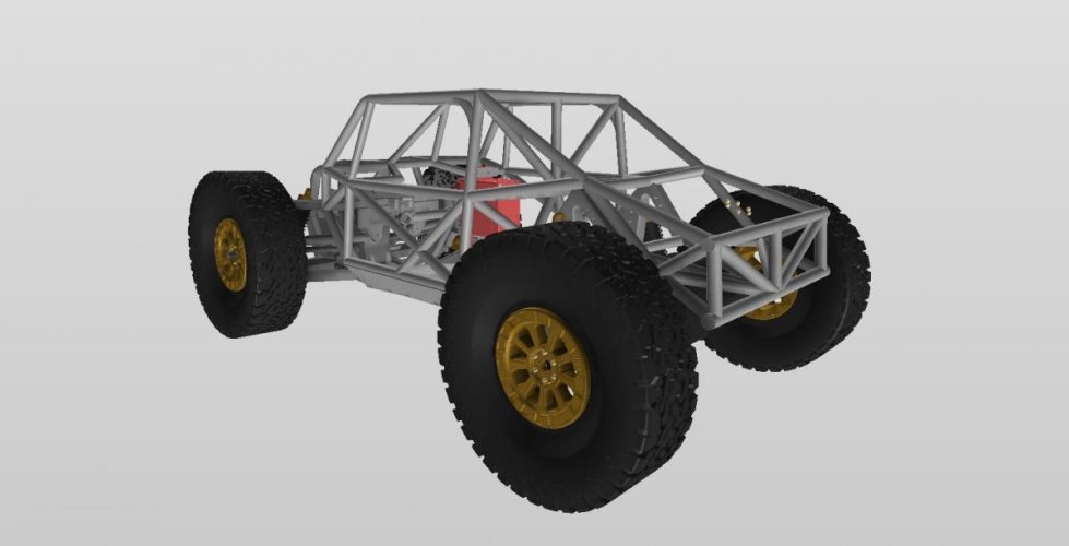
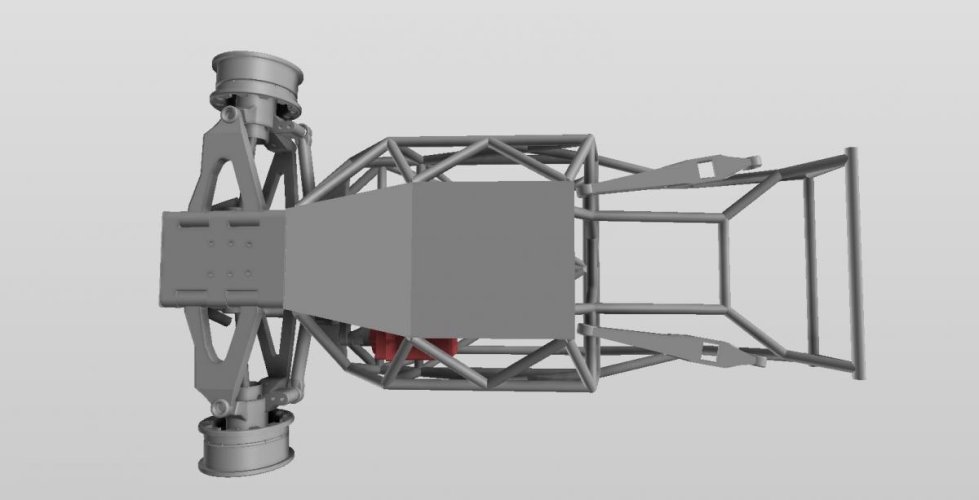
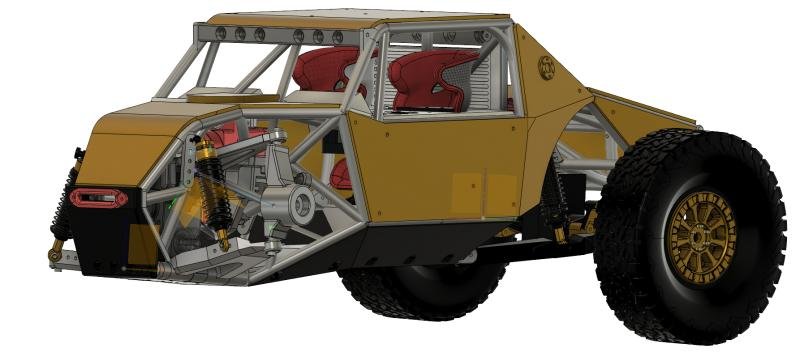
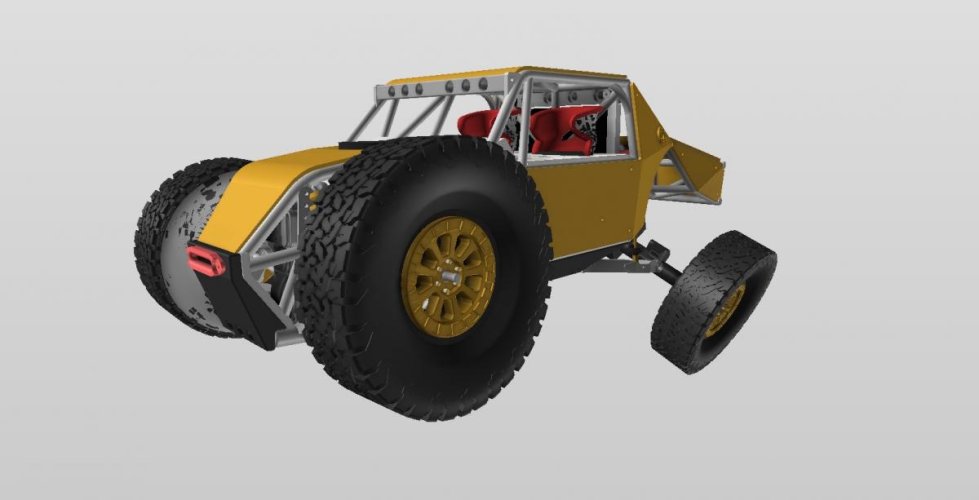
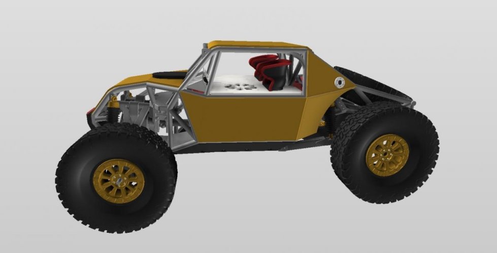
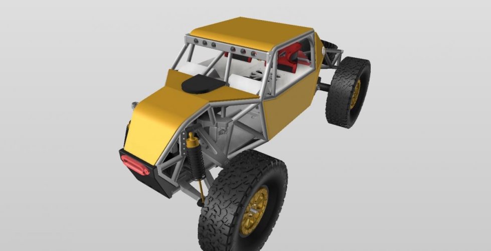
So having no idea where to even start something like this, I just parted out one of my other chassis designs in CAD, took out all the components and parts of the chassis I wouldn't need in the program and most of the front half and started designing. the chassis I threw in there was just to help me gauge space and where I had room to put things, it wasn't permanent. I would later get rid of that chassis and start designing around the new front end components. I designed the front end to be 120mm outside tire to outside tire which we've found to pretty much be the sweet spot.
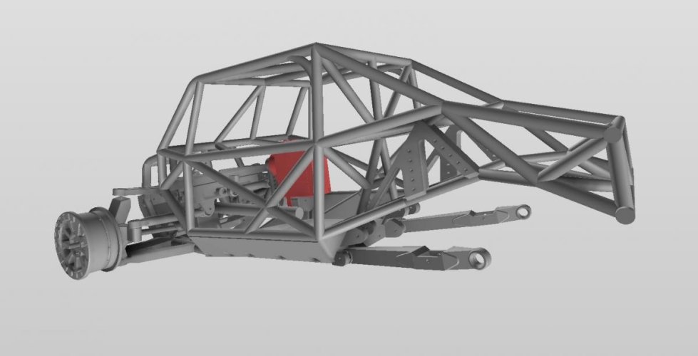
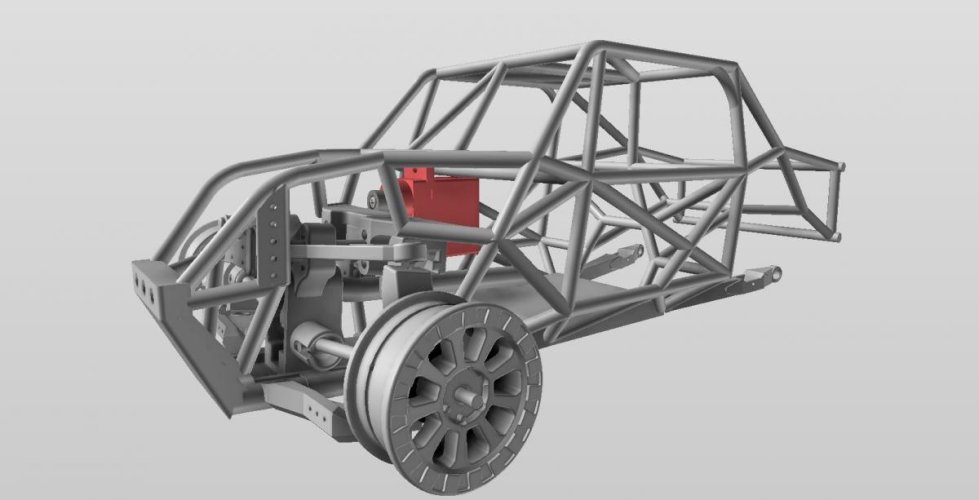
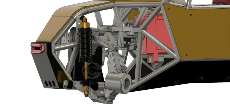
I wasn't quite able to get the front suspension travel I wanted out of the front end but its still more than a stock scx24 plus the rear end has WAY more travel than stock so the rear makes up for what I was trying to get out of the front due to the trailing arms in the rear.
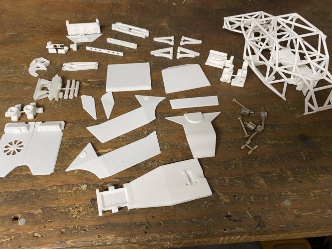
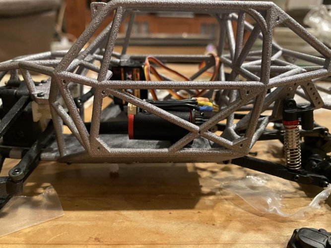
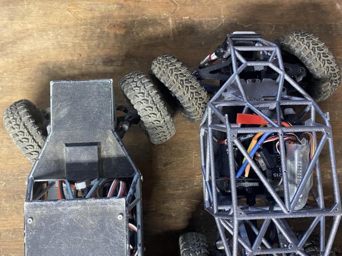
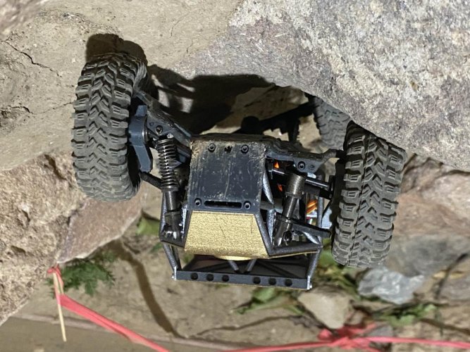
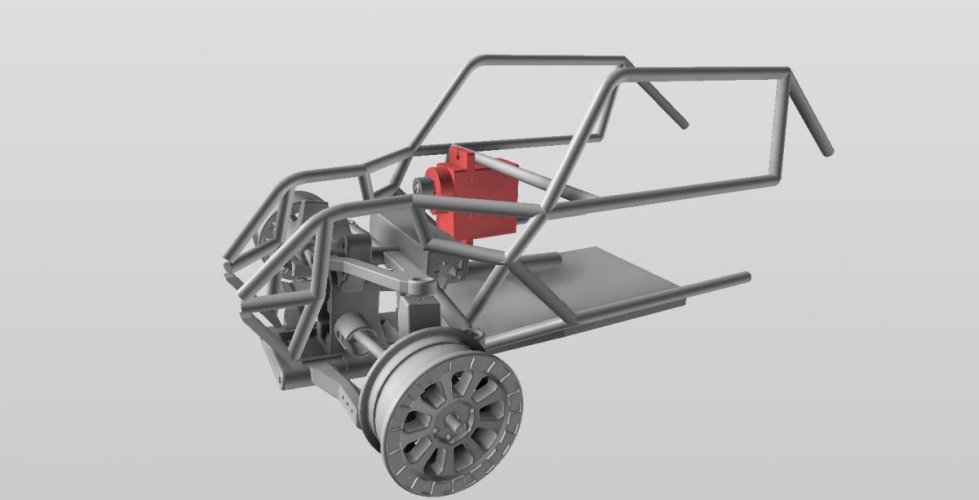
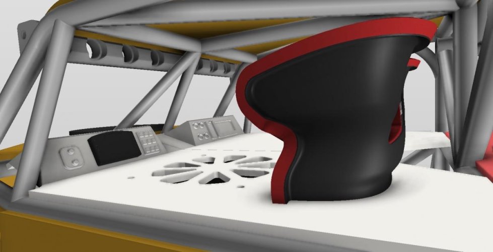
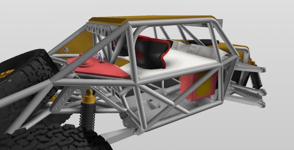
Another thing that I wanted was an all flat belly pan and a little wider to give more space in the cab for electronics.
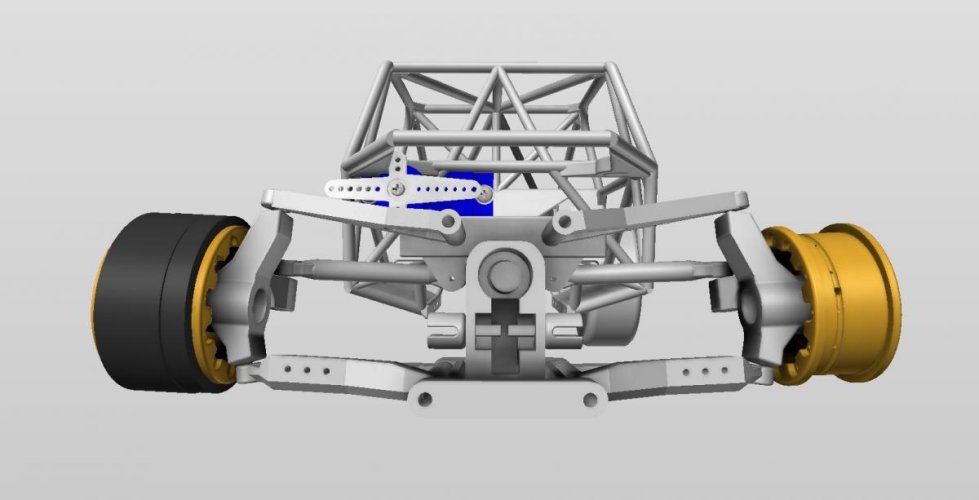
The car has just about the same steering ratio as stock which I felt like should be close to the same cause they steer pretty good once you throw an emax servo at it. Steering travel will be the same as stock or slightly more since I designed CVD axles for the front just like the bigger cars.
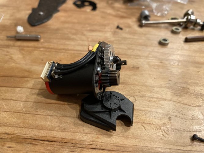
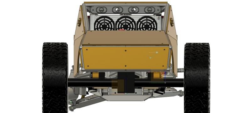
I also designed this to take a brushless system just like my U4 build that I posted up on here a few months back, this will use the same brushless system and a fan bolts to the bottom of the interior above the motor to help keep the motor cool.
I was just about to pull the trigger on getting everything printed then a guy on fb sent me a pair of cvd axles he found for another little car that were steel that were within a couple MM length of what I had designed. the axles I designed to get 3d printed then polished would cost about $115 so if I can make these work it would save myself and everyone else that gets one about $95. So I put a hold on ordering my kit until I get the axles in the mail, take some measurements and see if they're anything I can use, worst case I just bite the bullet for the 3D printed CVD front shafts I already have designed.
Enjoy some of these pics of the design process let me know what you guys think!
So having no idea where to even start something like this, I just parted out one of my other chassis designs in CAD, took out all the components and parts of the chassis I wouldn't need in the program and most of the front half and started designing. the chassis I threw in there was just to help me gauge space and where I had room to put things, it wasn't permanent. I would later get rid of that chassis and start designing around the new front end components. I designed the front end to be 120mm outside tire to outside tire which we've found to pretty much be the sweet spot.
I wasn't quite able to get the front suspension travel I wanted out of the front end but its still more than a stock scx24 plus the rear end has WAY more travel than stock so the rear makes up for what I was trying to get out of the front due to the trailing arms in the rear.
Another thing that I wanted was an all flat belly pan and a little wider to give more space in the cab for electronics.
The car has just about the same steering ratio as stock which I felt like should be close to the same cause they steer pretty good once you throw an emax servo at it. Steering travel will be the same as stock or slightly more since I designed CVD axles for the front just like the bigger cars.
I also designed this to take a brushless system just like my U4 build that I posted up on here a few months back, this will use the same brushless system and a fan bolts to the bottom of the interior above the motor to help keep the motor cool.
I was just about to pull the trigger on getting everything printed then a guy on fb sent me a pair of cvd axles he found for another little car that were steel that were within a couple MM length of what I had designed. the axles I designed to get 3d printed then polished would cost about $115 so if I can make these work it would save myself and everyone else that gets one about $95. So I put a hold on ordering my kit until I get the axles in the mail, take some measurements and see if they're anything I can use, worst case I just bite the bullet for the 3D printed CVD front shafts I already have designed.
Enjoy some of these pics of the design process let me know what you guys think!
Attachments
-
 IMG_1998.jpg48.4 KB · Views: 4,654
 -
 IMG_2167.jpg42.7 KB · Views: 4,491
 -
 IMG_2165.jpg53.2 KB · Views: 4,480
 -
 IMG_2164.jpg59.1 KB · Views: 4,649
 -
 IMG_2163.jpg43.4 KB · Views: 4,591
 -
 IMG_2136.jpg49.4 KB · Views: 4,594
 -
 IMG_2073.jpg39 KB · Views: 4,517
 -
 IMG_2071.jpg54.7 KB · Views: 4,606
 -
 IMG_2065.jpg40 KB · Views: 4,656
 -
 IMG_2010.jpg51.2 KB · Views: 4,662
 -
 IFS BULKHEAD v186.jpg36.3 KB · Views: 4,404
 -
 IFS BULKHEAD v186 REAR.jpg33 KB · Views: 4,284
 -
 IFS BULKHEAD v186 FRONT.jpg35.1 KB · Views: 4,473
 -
 IMG_2207.jpg43.9 KB · Views: 4,438
 -
 IMG_2198.jpg57 KB · Views: 4,548
 -
 IMG_2195.jpg44 KB · Views: 4,452
 -
 IMG_2194.jpg66.9 KB · Views: 4,384
 -
 IMG_2193.jpg44.5 KB · Views: 4,473
 -
 IMG_2192.jpg43.6 KB · Views: 5,017
 -
 IMG_2168.jpg38.9 KB · Views: 4,468

")