• Welcome to RCCrawler Forums.

    It looks like you're enjoying RCCrawler's Forums but haven't created an account yet. Why not take a minute to register for your own free account now? As a member you get free access to all of our forums and posts plus the ability to post your own messages, communicate directly with other members, and much more. Register now!

    Already a member? Login at the top of this page to stop seeing this message.

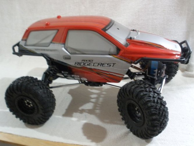
AX10 Gen2 Budget Re-build

Machined a servo mounting bracket and 3D printed a spacer to go between the servo bracket and the axle.
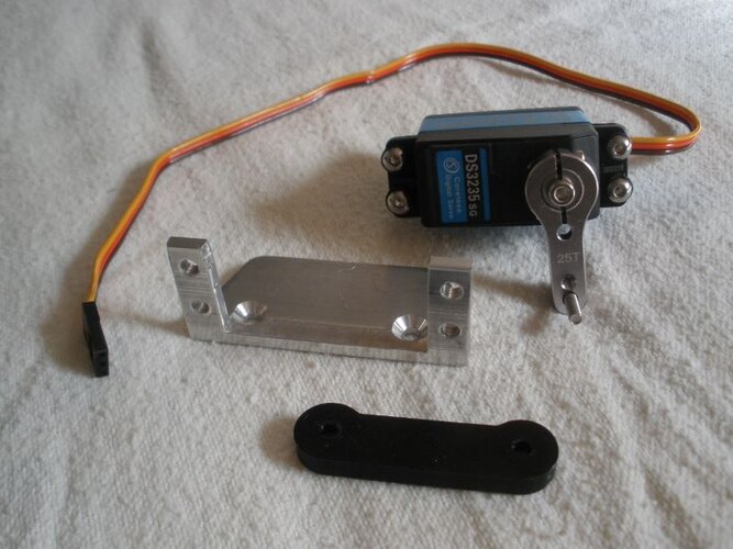
RCC-AX10-27.JPG

Not too difficult to machine the bracket. It is 1" x 1" x 1/8" thick aluminum angle. Milled out the center for the servo to fit in and drilled some holes. The 3D printed spacer is 0.200" thick to raise the servo up enough that the servo horn doesn't hit the drag link. The spacer has a relief on the bottom so it sits on the axle, not on the raised posts the servo bracket usually mounts to. I like doing it this way because it creates a nice solid platform for the bracket to bolt to.
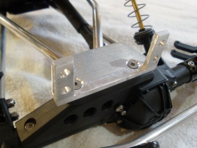
RCC-AX10-28.JPG

Servo mounted and steering link attached to the servo horn.
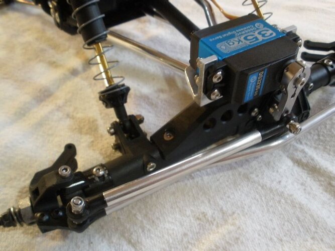
RCC-AX10-29.JPG

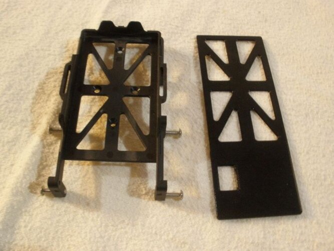
I noticed before I tore this all apart the battery tray is just slightly lower than one spot on the transmission so I 3D printed a 0.043" thick spacer to raise the battery enough to clear. I used a little glue to mate the spacer to the battery tray and clamped the two (2) together for overnight. The tray will get bolted to the chassis tomorrow.
RCC-AX10-30.JPG
 
The battery tray with the spacer glued in place.

RCC-AX10-31.JPG

And, battery tray mounted to the chassis. Where you see the rectangular hole is in the spacer, you can see the top of the transmission. My 5000 mAh batteries are long enough they sit over top of that spot. I didn't check my 2200 mAh batteries to see if they are short enough to clear.

RCC-AX10-32.JPG

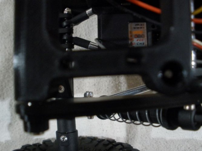
Wheels and tires installed, view from the front of the chassis.

RCC-AX10-33.JPG

View from the rear of the chassis. My next part of the project will be to 3D print a mounting plate for the electronics which will bolt on the rear of the chassis.

RCC-AX10-34.JPG
 
The battery tray with the spacer glued in place.

View attachment 508356

And, battery tray mounted to the chassis. Where you see the rectangular hole is in the spacer, you can see the top of the transmission. My 5000 mAh batteries are long enough they sit over top of that spot. I didn't check my 2200 mAh batteries to see if they are short enough to clear.

View attachment 508357

Wheels and tires installed, view from the front of the chassis.

View attachment 508358

View from the rear of the chassis. My next part of the project will be to 3D print a mounting plate for the electronics which will bolt on the rear of the chassis.
Looking good! Also, isn't there a little tray mount thingy that's supposed to go there specifically for that? Mine has one that I've got the ESC mount for and that's what I have everything mounted to (no receiver box though unfortunately).
 
Looking good! Also, isn't there a little tray mount thingy that's supposed to go there specifically for that? Mine has one that I've got the ESC mount for and that's what I have everything mounted to (no receiver box though unfortunately).
Yes, there is a tray/bracket/clip thingy that the ESC would mount to and a receiver box behind it (towards the rear). I don't like using receiver boxes because if water does get in there, I won't know until I have an electrical issue and open the box. All my electronics are chemically waterproofed and I've never had an issue doing it that way. In fact, my wife and I were on a trail beside a creek a few years ago and had to climb over a tree across the trail. She must have bumped the throttle and after getting over the tree we looked back to drive the trucks under the tree. Hers wasn't there and it took a minute to find it, under 2 feet of water in the creek. After rescuing it from the creek, she drove it the rest of the day. I blew everything off with compressed air after we got home and she is still using it today, with all those original electronics. So, I will be mounting the ESC, the receiver, a BEC and a DC-DC voltage converter/regulator to a 3D printed electronics bracket. With a little luck I hope to have that done today. If not today, then tomorrow.
 
Yes, there is a tray/bracket/clip thingy that the ESC would mount to and a receiver box behind it (towards the rear). I don't like using receiver boxes because if water does get in there, I won't know until I have an electrical issue and open the box. All my electronics are chemically waterproofed and I've never had an issue doing it that way. In fact, my wife and I were on a trail beside a creek a few years ago and had to climb over a tree across the trail. She must have bumped the throttle and after getting over the tree we looked back to drive the trucks under the tree. Hers wasn't there and it took a minute to find it, under 2 feet of water in the creek. After rescuing it from the creek, she drove it the rest of the day. I blew everything off with compressed air after we got home and she is still using it today, with all those original electronics. So, I will be mounting the ESC, the receiver, a BEC and a DC-DC voltage converter/regulator to a 3D printed electronics bracket. With a little luck I hope to have that done today. If not today, then tomorrow.
Oh dang that's rough. That actually does make a lot of sense, you've got me thinking now lol. I do have my receiver mounted out in the open, it's just on the backside of the ESC mount. A new mount plate would be pretty cool though.
 
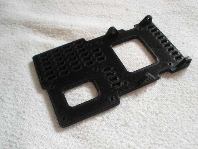
Started the day before breakfast. I've been designing the electronics mounting tray in the evenings as that seems to be the only time I have to sit at the computer. A few days ago I did a test print to see how it fit to the chassis. Of course it didn't but it did provide the information to make the modifications needed to make it fit. I wasn't totally confident it would fit so crossed my fingers and had at it. The mounting tray is about a 2-1/2 hour print so I had time to work on the the other items to be printed for the tray.

I did check the fit of the tray to the chassis before carrying on and it fit pretty good. The electronics need to be mounted before final install on the chassis.

RCC-AX10-35.JPG

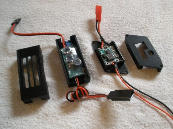
Here's the electronics and the 3D printed parts to hold the individual parts to the tray. At the top of the picture is the ESC and a cover to bolt it to the tray. Below on the right is the tray, the receiver with a cover, shown above the receiver, to bolt it to the tray. Then the BEC and beside it is a box for it to bolt to the tray. Lastly, is a DC-DC voltage converter/regulator with a box to bolt it on top of the BEC box. The BEC is dedicated to the steering servo and the DC-DC converter is adjustable and set at 6V to provide regulated voltage to power the LED lights that will be mounted on the body. I like using these DC-DC converters because it doesn't matter if I use 2 cell or 3 cell batteries, the voltage is always at 6V for the LEDs. These particular ones I use are rated at 4.5V to 28V input and adjustable output of 0.8V to 20V, and rated at 3 amps max. so not good for servos.

RCC-AX10-36.JPG

The ESC mounted to the electronics tray.

RCC-AX10-37.JPG

The receiver mounted to the tray.

RCC-AX10-38.JPG

This picture will give you an idea of how the BEC and the DC-DC Converter fit in their respective boxes for mounting.

RCC-AX10-39.JPG

The box for the DC-DC converter box looks a little strange but that is because the mounting holes line up with the mounting holes in the BEC box. The DC-DC Converter box piggybacks on the BEC box and the bolts go through both of them to the electronics tray.

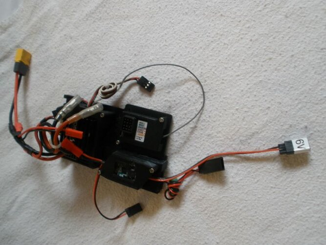
Electronics tray assembled and ready to be mounted to the chassis. Unfortunately, I ran out of time so that will wait until tomorrow to mount to the chassis. That's okay though. If you look closely at the center mount ear on the tray, I had to put M3 insert nuts in those holes as there is no room for nuts on the inside. The epoxy I put on them will have a chance to cure overnight. (y)

Just a little information on the 3D printed stuff, the seven (7) 3D printed items, took just under 6-1/2 hours to print.

RCC-AX10-40.JPG
 
Started the day before breakfast. I've been designing the electronics mounting tray in the evenings as that seems to be the only time I have to sit at the computer. A few days ago I did a test print to see how it fit to the chassis. Of course it didn't but it did provide the information to make the modifications needed to make it fit. I wasn't totally confident it would fit so crossed my fingers and had at it. The mounting tray is about a 2-1/2 hour print so I had time to work on the the other items to be printed for the tray.

I did check the fit of the tray to the chassis before carrying on and it fit pretty good. The electronics need to be mounted before final install on the chassis.

View attachment 508374

Here's the electronics and the 3D printed parts to hold the individual parts to the tray. At the top of the picture is the ESC and a cover to bolt it to the tray. Below on the right is the tray, the receiver with a cover, shown above the receiver, to bolt it to the tray. Then the BEC and beside it is a box for it to bolt to the tray. Lastly, is a DC-DC voltage converter/regulator with a box to bolt it on top of the BEC box. The BEC is dedicated to the steering servo and the DC-DC converter is adjustable and set at 6V to provide regulated voltage to power the LED lights that will be mounted on the body. I like using these DC-DC converters because it doesn't matter if I use 2 cell or 3 cell batteries, the voltage is always at 6V for the LEDs. These particular ones I use are rated at 4.5V to 28V input and adjustable output of 0.8V to 20V, and rated at 3 amps max. so not good for servos.

View attachment 508375

The ESC mounted to the electronics tray.

View attachment 508376

The receiver mounted to the tray.

View attachment 508377

This picture will give you an idea of how the BEC and the DC-DC Converter fit in their respective boxes for mounting.

View attachment 508378

The box for the DC-DC converter box looks a little strange but that is because the mounting holes line up with the mounting holes in the BEC box. The DC-DC Converter box piggybacks on the BEC box and the bolts go through both of them to the electronics tray.

Electronics tray assembled and ready to be mounted to the chassis. Unfortunately, I ran out of time so that will wait until tomorrow to mount to the chassis. That's okay though. If you look closely at the center mount ear on the tray, I had to put M3 insert nuts in those holes as there is no room for nuts on the inside. The epoxy I put on them will have a chance to cure overnight. (y)

Just a little information on the 3D printed stuff, the seven (7) 3D printed items, took just under 6-1/2 hours to print.

View attachment 508379
That looks extremely good, I wish I knew how model and stuff to make something like that. I'm so tempted to pick up a 3d printer and try to experiment with this kinda stuff.
 
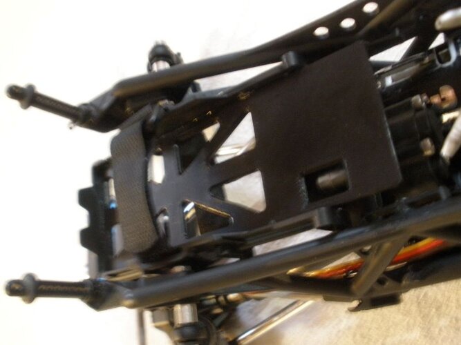
The electronics tray is bolted to the chassis now.

RCC-AX10-41.JPG

RCC-AX10-42.JPG

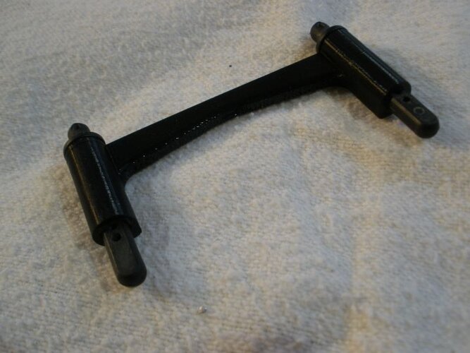
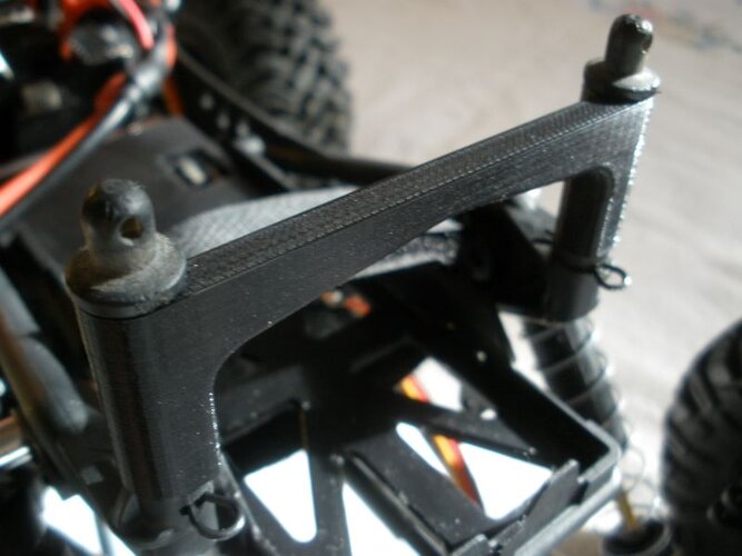
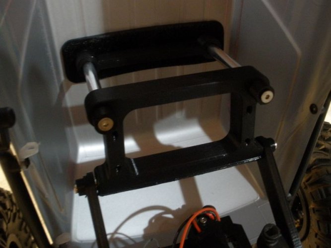
I 3D printed a brace to tie the two (2) front body posts together. The body posts are now perfectly spaced to the front mounting holes in the body. I think it makes it easier to set the body in place.
RCC-AX10-47.JPG

RCC-AX10-48.JPG

RCC-AX10-49.JPG

RCC-AX10-50.JPG

RCC-AX10-51.JPG

This pretty much completes the chassis. I now have a rolling/driving chassis.

I'll be working on the body now - LED lights and maybe a couple of other things I have ideas for. Lights for sure . . . . . "ideas", maybe. I'll see how it goes.
 
After saying I would be working on lights for sure, I decided to work on one of my "ideas" instead.

I've hinged to rear of the bodies on a few of my trucks and wanted to do the same with this one. The AX10 is a bit more challenging as there is no chassis rail extending to the back of the body. Took a while to formulate a plan and a whole lot longer to get the geometry figured out.

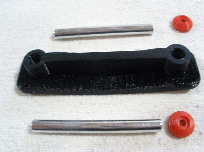
Machined some body posts and 3D printed a mounting plate, washers for the top of the body, chassis extensions, and a hinge plate.

RCC-AX10-52.JPG

The body mounting plate, body posts, and washers were done first. This part was reasonably easy.

RCC-AX10-53.JPG

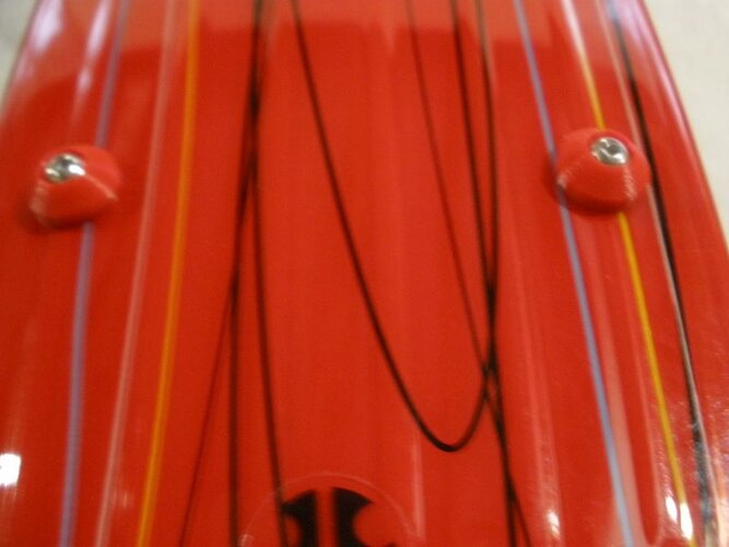
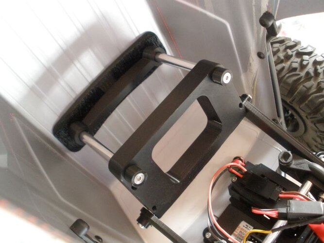
The body mounting plate and body posts assembled to the inside of the body.

RCC-AX10-54.JPG

The washers are larger than the body post holes in the body. The screws go through the top of the body, through the body mounting plate, and into tapped holes at the end of the aluminum body posts.

RCC-AX10-55.JPG

The brackets to mount the hinge plate are bolted to the chassis using the holes to mount the shocks. You can also see the aluminum round bar cross-brace I use to stiffen up the chassis where the shocks are mounted.

RCC-AX10-56.JPG

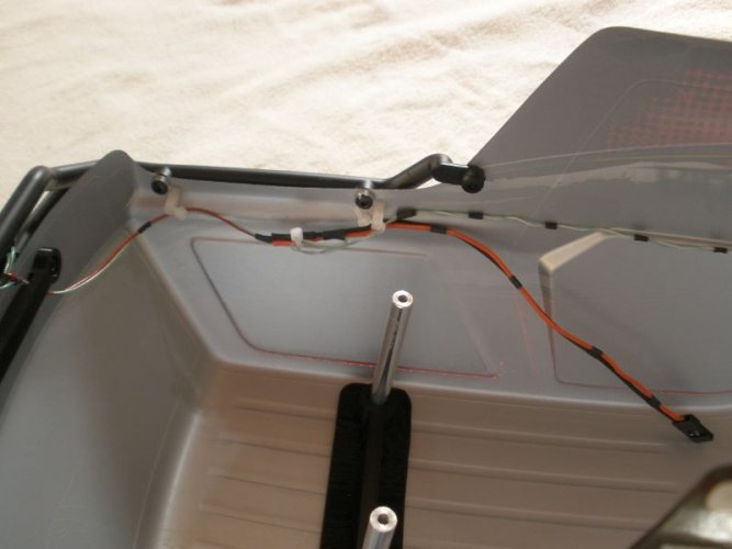
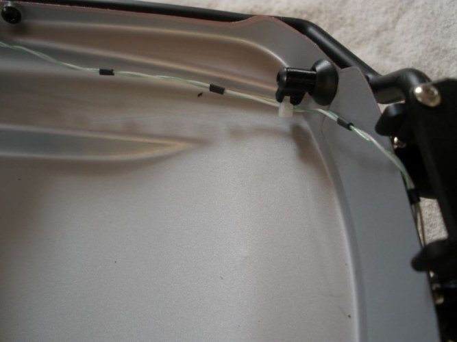
This is a modified hinge plate that was done after I had assembled the hinge assembly. I decided to add the two (2) slots down each side to use to zip tie the wiring for the lights to the hinge.

RCC-AX10-57.JPG

The hinge plate installed on the brackets mounted to the chassis. The hinge plate probably didn't need to be that "heavy" but it was way easier to print than anything else I came up with. Oh-oh, I think I outthought myself here. When the hinge is "down", the zip ties would interfere with the brackets supporting the hinge. I'll have to think about this. I see another 4 hour print coming up.

RCC-AX10-58.JPG

Everything for the hinged body mount assembled. The spacers on the bottom of the hinge plate lineup with the supports for the original body post mounting and just touch the supports when the body is closed. My idea is, any force from rollovers, etc., won't be taken entirely by the hinge assembly.

RCC-AX10-59.JPG

I got lucky and dimensionally everything worked out exactly right. The body drops perfectly onto the front body pins.

RCC-AX10-60.JPG

At this point, the last thing I need to do is the front and rear lights. I have designs for the front and rear light buckets I need to 3D print and then wire the LEDs in. That might take a while as well as I have some other commitments this week.
 
I had a chance to get back to this today. I redesigned the body hinge plate to have clearance for the zip ties that will hold the wiring for the headlights and taillights in place. Once I decided on the new design, it only took about five (5) minutes to make the changes to the 3D file. Then a three (3) hour print time, and, done.

RCC-AX10-61.JPG

Replaced the old hinge plate with the new one and you can see the clearance I have now between the hinge plate and the hinge mounting brackets. Should work okay I think.

RCC-AX10-62.JPG

Re-mounted the body and done.

RCC-AX10-63.JPG

Didn't take a picture but after mounting the body, I removed it again as it will be easier to get the headlights, taillights, and wiring done with the body off the chassis.

I'll 3D print the headlight and taillight buckets in the next day or so and get the LEDs wired in.
 
I got the headlight and taillight buckets printed and ready to mount the LEDs. The taillight buckets and the brace to mount on the inside of the body as a stiffener for the rear bumper are on the left and the headlight buckets are on the right with a couple of bolt-on LED retainers.

I had 3 or 4 different designs for the taillight buckets before I settled on this design. Simple and works well with the rear bumper. At least I think so.

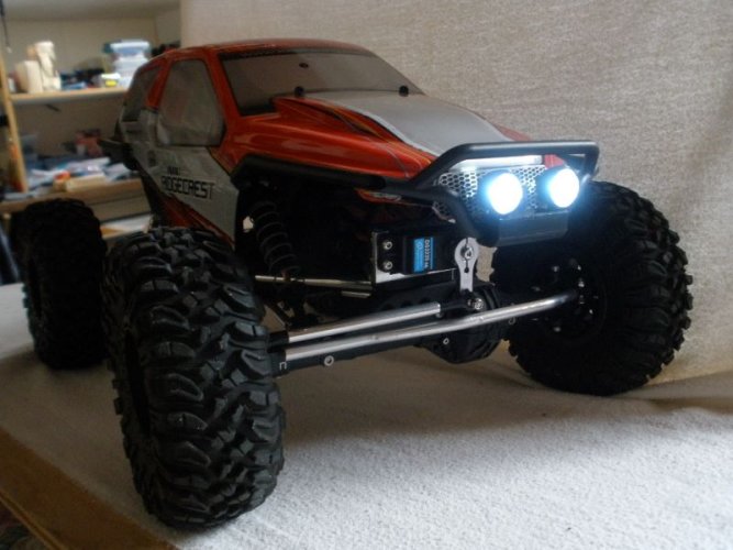
The headlight buckets will be mounted to the front bumper using the holes that the individual Axial light buckets were supposed to mount to. I don't know how Axial expected that to work without hacking up the body to clear the light buckets. I think my design is a better idea.

RCC-AX10-64.JPG

Headlights with the LEDs wired and mounted. The headlight lenses are 3D printed with clear filament. I couldn't find a way to get them to show up in a photo by themselves.

RCC-AX10-65.JPG

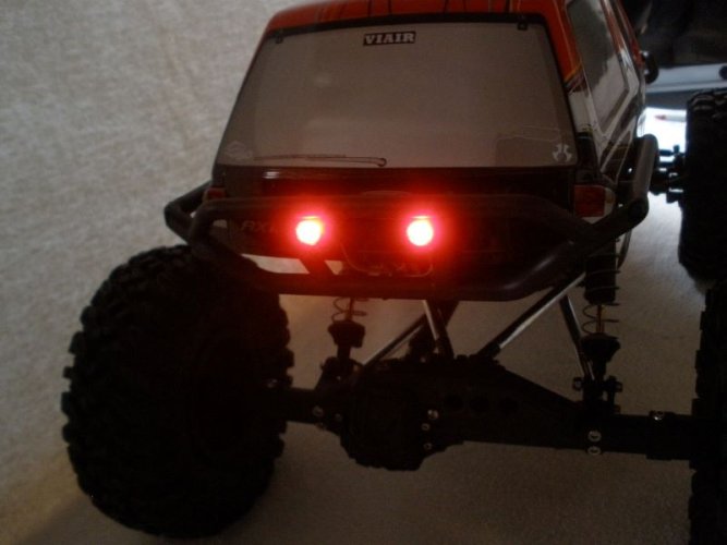
And, taillights with LEDs wired and mounted. As with the headlight lenses, the taillight lenses are 3D printed with clear filament.

RCC-AX10-66.JPG
 
Back
Top