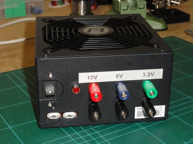
Hi everyone,
Took my time, but here is my build up:
As you know, this topic is not a new one, and I found this thread on RCC to be most useful. I read it from the start and took notes along the way, with a bit of added research elsewhere
>HERE<
I thought I would documenting my recent mod.
First of all, why do this?
Well, recently a friend (Splat) and I both purchased a new battery charger which can do 4 batteries at once. It's a Hitec X4 AC Plus - details
>HERE<
This unit has built in AC power, but only for 110V (USA). So we needed to power it from a 12V DC source as here in Australia we run 240V AC.
We could have gone out and purchased a purpose built 12VDC power supply, but they are pretty darn expensive (around the $200 mark for a good unit).
A computer power supply (PSU) is very cheap and provides a very stable and efficient power feed that suited our needs perfectly.
Anyways, on to the mod.
WARNING: PSU's can hold a charge for a short period of time. This charge can KILL or INJURE. Please ensure you understand these risks and know how to mitigate them before beginning any work.
First, get a PSU. I had an old unit sitting around home that I modded up for Splat. This was my first mod and worked a treat.
Once I had "practiced" on Splat, I wanted to make sure my own unit was a top notch job.
I splashed out on a new PSU which had a high Amp capacity on the 12V rail.
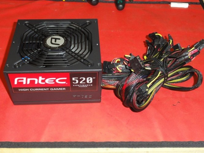
I picked this unit up locally in Australia from ARC Computers for $79
>LINK<
The reason I chose this unit:
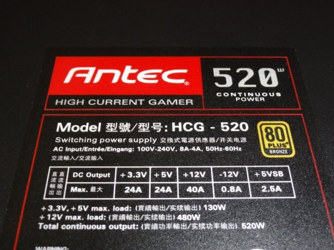
40A on the +12V rail!
NOTE: There is also NO minimum load requirements for any of the DC outputs
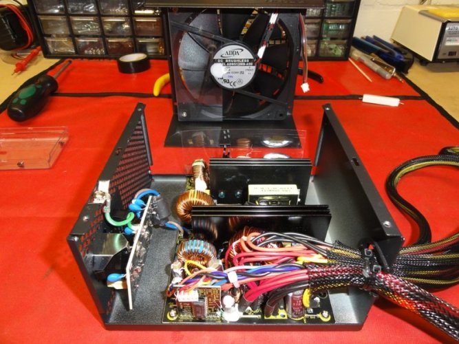
There were some added benefits to buying this PSU also, one of which was the simplicity of the internal layout and the ample space inside the case:

One thing I learnt while building up Splats unit was to take a close look at the ATX connector plug on the PSU before cutting any wires off.
You need to identify any doubled up wires and take note of them.
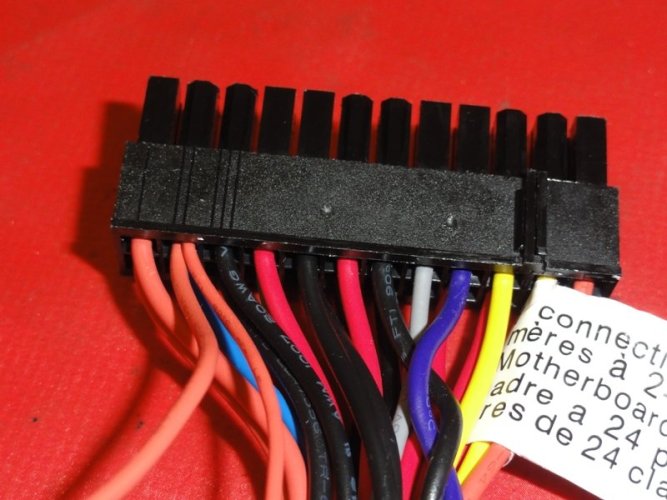
Here you can see the double orange wires. The smaller gauge wire is the 3.3V sensing wire for this PSU. On some older models it could be brown - check the full wiring guides from the two links at the top of this post for more information.
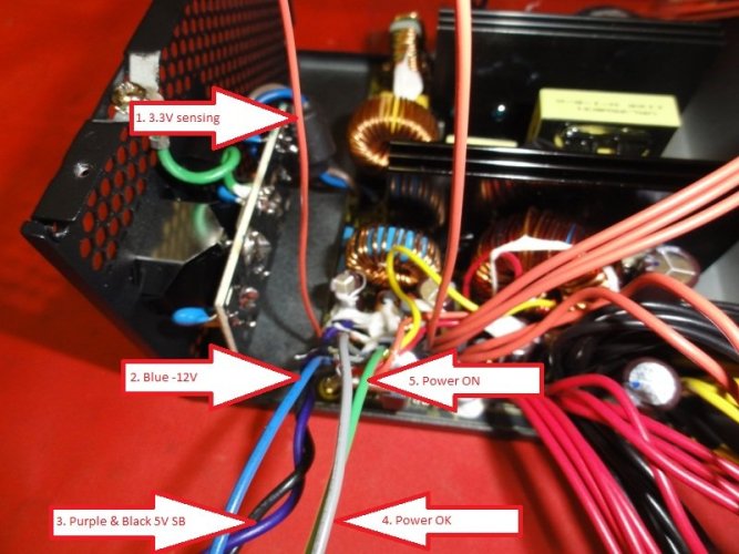
I traced this wire to the circuit board and set it aside along with some others:
1. Orange 3.3V sensing wire
2. Blue -12V (Not used in my mod)
3. Purple & Black +5V Stand By
4. Gray Power OK
5. Green Power ON
You can now also group together the coloured wires:
1. Orange = 3.3V
2. Red = 5V
3. Yellow = 12V
4. Black = Ground
Next up it was time to start chopping off excess wires.
You need to be very careful that you don't cut off too many wires and leave yourself missing some required wiring for the mods.
Also, make sure that you leave plenty of length in the remaining wires to allow you to position things where you need them.

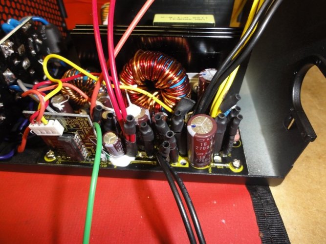
Next we take the 3.3V sensing wire and just join it to an orange 3.3V wire. Basically just simulating the join from the ATX plug as shown earlier:

Being Mr Safety conscious I then took the time to insulate all the exposed wiring with some heatshrink:
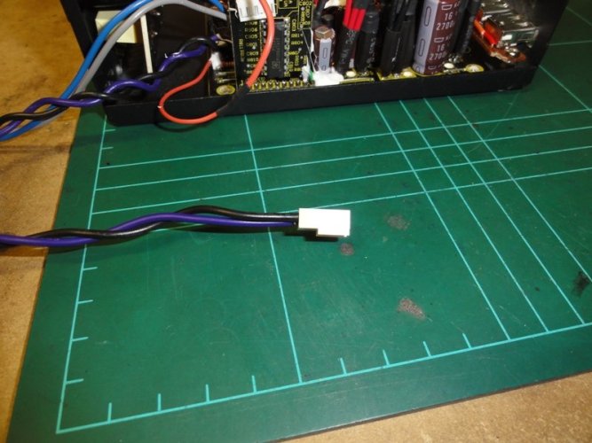
I put a plug onto the +5V SB (Purple and Black) wires to allow me to connect/disconnect it from the USB ports - just for ease of assembly/disassembly of the PSU:
I quickly made up a little circuit board with a couple of USB ports on it:


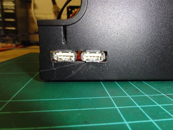
The wiring for the USB is very simple.
Purple is +5V, Black is ground
Purple goes to Pin1
Black goes to Pin4
Then also join Pin2 to Pin3 on the circuit.
Check
>HERE< for more details on the USB Wiring.
By wiring up the USB like this you can use the ports to charge most USB devices - mobile phones etc.
Then it was just a matter of drilling all the holes for the terminals, LED and making a mount for the switch:
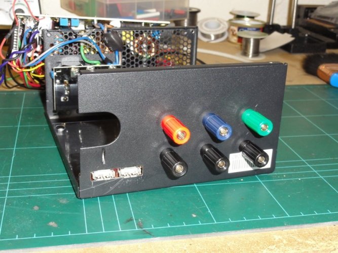


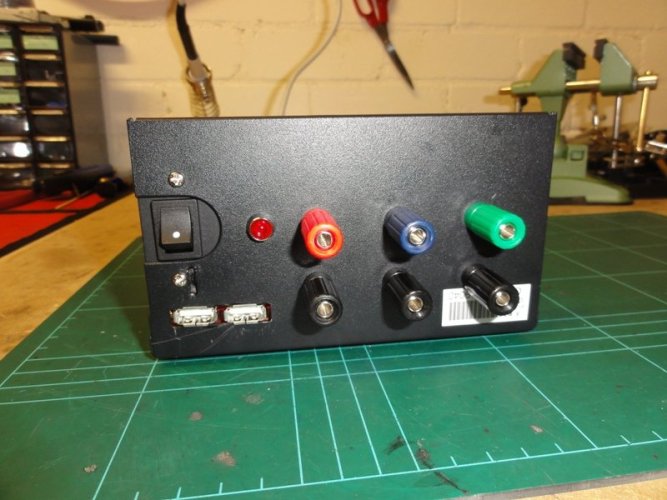
Connect up all the wires:

Orange wire to the 3.3V terminal
Red wire to the 5V terminal
Yellow wire to the 12V terminal
Black wires to all the Ground terminals
Gray wire to the LED positive leg
Black wire to a 220 ohm Resistor connected to the LED negative leg
Green wire to the Switch
Black wire to the switch
Purple & Black to the USB ports
NOTE: As this PSU does not have minimum load requirements on any of the outputs I did not need to install the 10ohm 10w resistor as per the instructions from the RCC and other links at the top of this post.
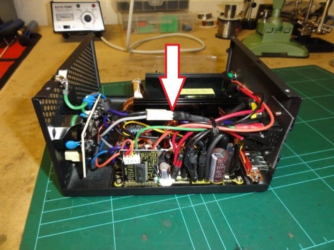
NOTE: The arrow shows another plug I used for the LED wires, hidden under the heatshrink is my 220 ohm resistor
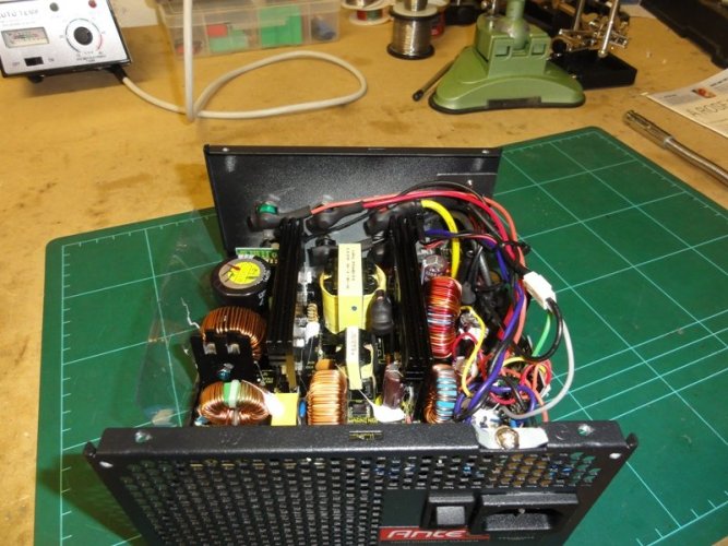
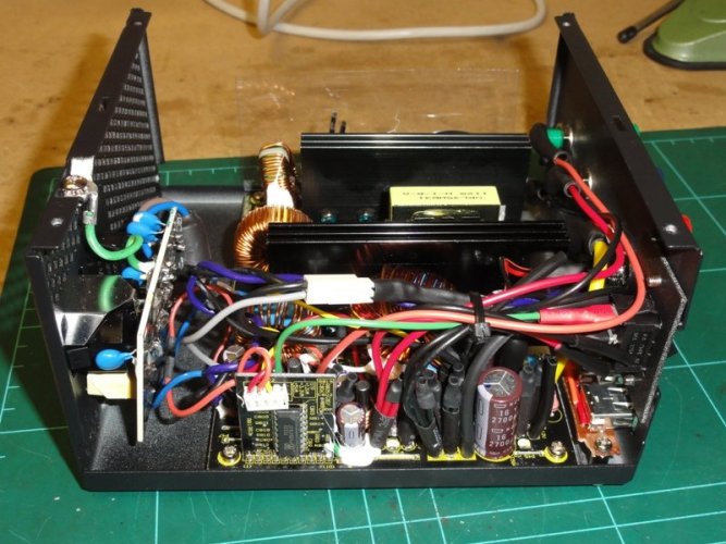
Another added benefit to getting this PSU was that it was VERY easy to wire in some thicker gauge wires for my 12V terminal to handle the high AMP draws.
Here you can see some extra holes for wire:
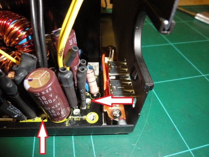
This enabled me to easily connect in some much larger wire:
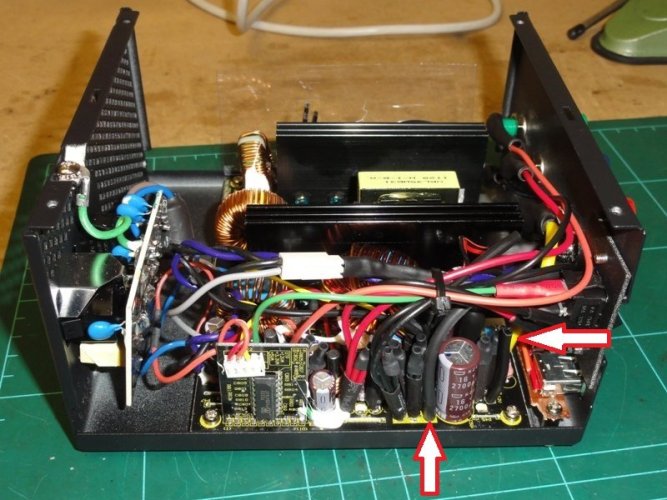
Then tidy it all up and test it out:
