• Welcome to RCCrawler Forums.

    It looks like you're enjoying RCCrawler's Forums but haven't created an account yet. Why not take a minute to register for your own free account now? As a member you get free access to all of our forums and posts plus the ability to post your own messages, communicate directly with other members, and much more. Register now!

    Already a member? Login at the top of this page to stop seeing this message.

unimogrob's gelande II landcruiser build

unimogrob16

Newbie
Joined
Jan 11, 2016
Messages
36
Location
california
Getting back into the RC building after a long while.
New to this forum, but not to RC and modeling in general.
Been building model planes, ships, cars since I was a kid.
Then moved on to the real cars, mainly restoring 2 fj-40 landcruisers, and 2 Mercedes 404 unimogs.
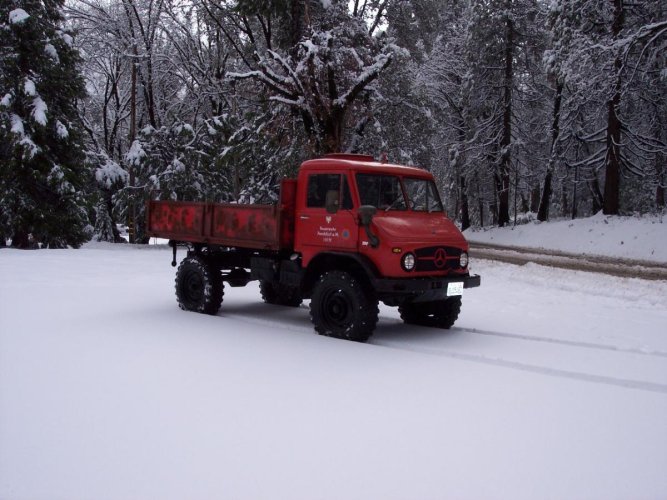
I currently have a restored from the frame up 1973 fj-40, and a 1966 Unimog 404.115 hardcab with the cargo bed.
When I first started looking for a kit years ago, the Tamiya CR-01 landcruiser and unimog kits were available, but just did not look right.
Then I recently stumbled across the RC4WD gelande II cruiser. Had to get it.
So, I will dive into this one and maybe when that's done I will do a scratchbuild of the unimog, since there is no kit available in the 404 version. Some of the mods I will do to the Cruiser have been done, some have not. I have been looking and reading the threads on this kit and there are some great builds out there.

This is the list for now.

Frame and chassis:
1. Fabricate new rear bumper to match 1:1
2. fabricate new front bumper to match 1:1 (maybe-not sure yet)
3. Change over to leaf springs and shackles.
4. Relocate rear shocks.
5. Change wheel and tire combo. Planning on G-made 1.9 wheels. Not sure about tires yet.

Body:
1. Cut doors off to match 1:1
2. Cut out rear cargo humps to enlarge area, cover with parts from pardonmynoob.
3. Fabricate custom roll bar to match 1:1
4. Cut rear fender opening up a little (maybe). Attach flares.
5. Try to modify seating area to fit bucket seats
6. Re-do dash . Either modify existing, or fabricate complete new dash to match 1:1. I don't know how they got the dash area so wrong on the kit.

That covers most of it.
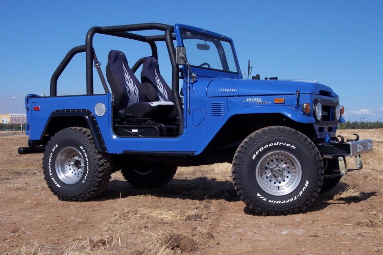
Inspiration will be my full size blue 1973

A few notes on the model itself.
I made 12 separate measurements on the model and on the 1:1 to check scale. It comes out to be 1/7.6 scale.
So I will round it off to 1/8 to do the custom adds, and just use my eye to see if it looks right.

Soon as I get started I will post pics.

Rob.
 

Attachments

  • 100_1213.jpg
    100_1213.jpg
    164 KB · Views: 1,285
  • 100904-20.jpg
    100904-20.jpg
    142.7 KB · Views: 1,398
Last edited:
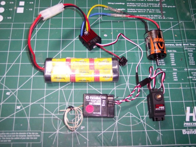
Had a little time yesterday before the big game and hooked up all my electronics. Everything works.
I am using an old school radio from a previous build that was in my used up pile.
It is an 1990's two stick Futaba Attack radio and Rx. (forgot to put it in the pic).I have used the 2 stick for my planes and cars, and prefer it. Never got used to the trigger and wheel. This is going to be a backyard occasional use rig, so it fits the bill.


Also did some more measuring and found the rear bed corners are too small. The radius needs to be bigger to look right. Might have to move the rear marker lights also.
Also going to fabricate a rear tire carrier and license plate holder.
Lot of work ahead.

More to come...

Rob.
 

Attachments

  • electrics.jpg
    electrics.jpg
    156.3 KB · Views: 1,289
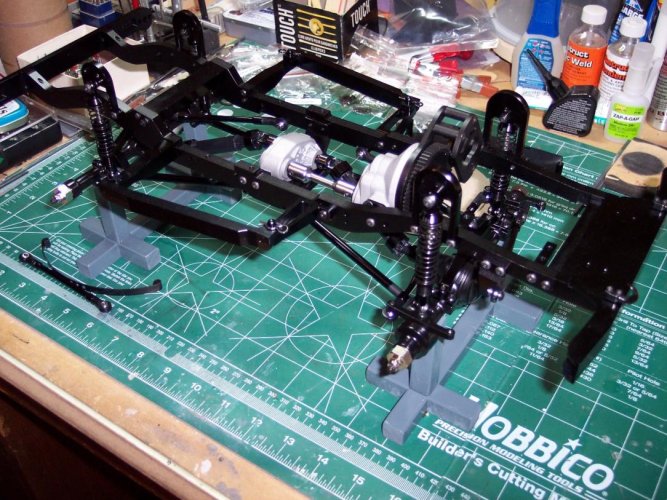
Basic chassis now complete. Now with the body on , I can see where to line up the shackle mounts. Still waiting for rims and tires.
Since I have the 1:1 cruiser sitting in the garage, I can take measurements to locate things. The overall wheelbase should be 2286 mm. scaled to 287mm ish. model comes in at 273 mm. Front seems to locate OK. Might have to move rear back a touch. Depends on how the tire fits the wheel well. Which might get opened up to match the 1:1.
Now get to take it all apart and put on springs and shackles. When the postman gets here that is.
More to come.
 

Attachments

  • frame2 (1).jpg
    frame2 (1).jpg
    184.2 KB · Views: 1,229
  • body1.jpg
    body1.jpg
    161.2 KB · Views: 1,235
  • frame2 (2).jpg
    frame2 (2).jpg
    182.3 KB · Views: 1,257
Yes, been busy finishing another project, so haven't had much time to spend on this one.
Been able to get shackle placements in the correct place and made a few test springs, so should have new pics up soon.
 
Finally done with springs and shackles.
built my own springs using an old bandsaw blade. Cut it to length and width , then heat bent the ends ,then put in jig to heat to final curve.The helper spings are made from a thinner gauge blade and held with a brass strip.

springs1.jpg
jig1.jpg
springs2.jpg


Mounted on the shackles, they seem to have the right amount of flex. We will see once it is up and running.

front1.jpg
rear1.jpg

I made a new crossmember for the rear shocks out of a piece of 1/4 x 3/8 aluminum I had. Machined the ends to fit in the frame. Also notched the front crossmember to fit the shackles.I don't have a milling machine, but a well tuned table saw with a sharp blade does nice work.


rear2.jpg
notch1.jpg


Last piece was a new carrier for the tranny. Thanks to pardonmynoob for the idea.

trans.jpg

I might make a new front bumper to match my 1:1, or modify the original.
Also might move the front shock hoops forward a few MM as the shocks are not vertical now. I might even fab up something different, like the 1:1. A little more tinkering. I moved the front axle forward and the rear axle back a few.

I think the stanch and height are just about right.

body.jpg

After a few more detail on the frame, it will be on to the body mods.
More fun ahead.
 
I love how you notched the front frame with a table saw!! Great idea! Is that a special blade? Nice clean notch!! I don't even have the luxury of a table saw.

Is there a reason to make a new transmission mount? or just to save weight?
 
I love how you notched the front frame with a table saw!! Great idea! Is that a special blade? Nice clean notch!! I don't even have the luxury of a table saw.

Is there a reason to make a new transmission mount? or just to save weight?

The stock mount was just too bulky looking for me. I plan on making a skid plate and attaching it that.

Blade is a flat bottom carbide blade. Used for woodworking mostly. The teeth are ground flat, hence a nice flat, square cut. I removed most of the material on my scroll saw fitted with a 20tpi blade. Only had to remove a little bit on the table saw to make it nice and neat. I did not need to remove all the way across, just enough for the nut and bolt to clear.
 
Cool thanks for the info. I don't have any of those and will try with TF2 hangers and shackles, I guess. I am a newbie and scared of trying this but also want to. :)
 
I mentioned I was going to re-locate the front shock mounts.
I got creative and made a test piece out of styrene to test fit and clearance.
Seems to be ok. Height is the same as on the stock hoop, but moved forward utilizing two holes already in the frame. The drivers side does not have the holes, but will drill and tap those.
mount1.jpg
mount2.jpg

the shock has been moved to the front on the axle.
mount3.jpg

I checked and the steering rod from the servo will clear. I did not have it in the pic.
Now time to put on my metalworking hat and fab something up. Probably out of aluminum.
I will post pics when I have more completed.
 
Well, after several attempts, the shock towers are done.
I tried making out of aluminum, but no good.
I finally made them out of steel. 14 and 18 gauge and a short piece of 1/4 rod drilled out.

Tack welded
st1.jpg
sd2.jpg

Then silver brazed
sd3.jpg
sd4.jpg

Then some grinding and sanding with the dremel, the primed, painted , and installed.
sd5.jpg
sd6.jpg

I think they turned out good. I know they are strong, I caught one on the wire wheel and it went bouncing across the floor. No damage except a small ding.
Next is a skid plate under the trans mount, and a bumper modification.
 
Very nice work with the limited tooling you have. "thumbsup"

The table saw idea scares me, great job and way to think out of the box! I assume you still have all your fingers? :ror:
 
Yes very nice work so far!! I too would be afraid of the table saw method! I am trying to figure a different method for the front leaf hanger mounts on my build, that has yet to be started..lol.
 
Yes, all fingers accounted for.
Been working with power tools for over 35 years. Only a few nicks.
Just have to respect the tools your working with. And always be safe.
 
338990d1457997648-rear1.jpg


I would love a custom rear cross member like the one you made for the shocks. I am not sure what I will do to mount mine. Maybe like another guy did, cut the tray off the back member and rotated it.
 
Ok. Finally got all the pieces cut for the front and rear bumper. Both are modeled after my 1:1 '73 landcruiser.
Lots of layout, measuring, cutting, welding, grinding and drilling.


front bumper is made out of a piece of 5/8" square tubing. Brackets are 14 and 18 gauge. Hooks are from the kit, shackles are hot racing.
front bump 2.jpg


Rear bumper is made from a piece of 1/2 " tubing with plugs welded on and rounded over. Hitch receiver is bent 18 gauge.
rear bump.jpg

I will post more pics once I get them tack welded and brazed.
 
Back
Top