The cab is sick! Should look like a beast when you’re done.
Sent from my iPhone using Tapatalk
Sent from my iPhone using Tapatalk
The cab's arrived :mrgreen:


(I'm making a single-post thread-jack) - those cabs are SO cool, I would love to build a performance crawler using one with an external cage and a shorter bed..."thumbsup" (but I haven't got the skills!)
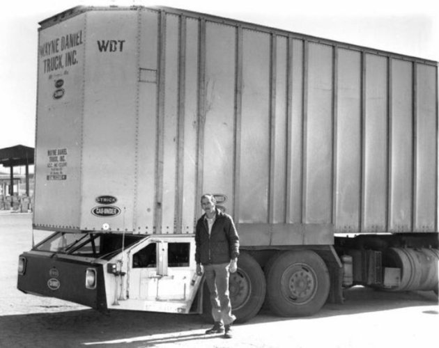
The other day I saw this incredible cab-under truck - much LESS suited for rough terrain, but kinda nifty, nonetheless:
It was a prototype from Strick and it was meant to have a trailer sitting on top, and another being towed behind:
Hey, Jim - question - is that cab you got the Cross RC HG-P802 cab?
Enquiring minds want to know!
;-)
The cab is sick! Should look like a beast when you’re done.
Sent from my iPhone using Tapatalk
Indeed it is, I found it on eBay: https://www.ebay.com/itm/325164586754 It comes green or sand (beige) by the way.Looks like the HG P802 cab to me!
Hey, Jim - question - is that cab you got the Cross RC HG-P802 cab?
Enquiring minds want to know!
;-)
") but did manage to reassemble the chassis rails and install the axle #1 link mount.
but did manage to reassemble the chassis rails and install the axle #1 link mount.


I like where this is going so far but now you've got me wondering if it would be easier the make a a similar TRX6(8) by cutting two 6s in the middle and splicing the two rear ends together.
I don't have my 6 in front of me so I can't really visualize it but I imagine it would make it simpler to configure the twin axle/link setup.

This might help with visualization: my extended chassis alongside the stock TRX-6 one.
![url])](/forums/proxy.php?image=http%3A%2F%2F%5BImgur%5D%28%5Burl%5Dhttps%3A%2F%2Fi.imgur.com%2F6sqPOOM.jpg%5B%2Furl%5D%29&hash=954fb8cc31934ab89bab40d7bb4f92bd)
And I think you're onto something! If one were to cut the stock TRX-6 chassis in the middle of where the skip plate is and splice in another rear section to mirror the existing one, then the problems I had getting the link mount for axle #1 to fit go away!!
You'd need to make sure your joint was really solid as the center of the chassi would be subject to the largest forces due to the long "lever arm" effect. I live in an apartment and don't have the means to braze, but that would probably be the way to go.
The only remaining issue would be mounting the front bumper which might or might not end up too high depending on the body/cab being used.
Thanks for the contribution, others deciding to tackle this project might benefit!!
Now that I think about to though, I'm not sure how well you could mount the "rear" four link of the second axle to the front of the center skid.
Sent from my LM-V600 using Tapatalk


That makes sense. Like I said, it's hard for me to visualize the ideas floating around in my head without my 6 in front of me. You're pictures are very helpful.The "rear four link" would mount just as it does on the TRX-6... just in the reverse direction. That wouldn't be a problem, though to avoid bump steer issues, better to turn axle #1 into a 3-link + panhard rod which is easily accomplished with some minor trimming as per below.