SurlyBurly
Pebble Pounder

Pretty impressive stuff man. Did you create that model of the axle and ring gears?
Yup - the axle is just a close replica for mocking, the rest is at precise scale. Was required to designed it!
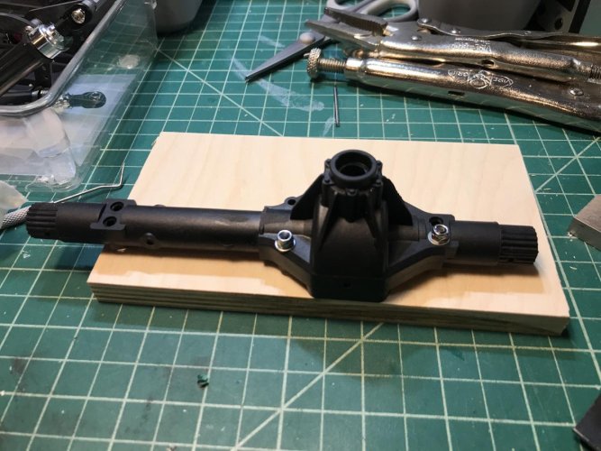
I like where you're going with that cover... and the whole car for that matter. In the last pic, is the face of the cover 1 piece with the bottom? Are the bearing caps incorporated into the cover now that the lower bearing cap bolt holes have been cut? Is the underside just held on by 2 screws after drilling upwards into the housing? I've got a couple ar60 housings (that I previously wore through the bottom of) laying around that I wouldn't mind experimenting with.


Hey. The folk from Progressive RC didn't like that I a made copy of their design (The Barber), so I'm checking how to share my version without going over them. You can still buy theirs in the meantime.What happened to the diff covers on your Shapeways? I saw them earlier, then refreshed the page and they're gone. I'd really like to give one a try and if it goes smoothly on my worn out plastic axle, maybe even try it on a Chinese "steel" (potmetal) housing. I think with a full width truss on top, it could still stand up to some abuse.