Voodoobrew
I wanna be Dave
Updated: August/19/2021
A different less Drunk tutorial can be found on Github here
Here is a video I made you can watch too, it also talks about using a flight controller to update and configure the firmware. It is where you would set your motor KV and change the startup power.
(At the moment it is outdated and shows using the power from the ST-link, Don't use power from the ST-link, they burn up too easy.)
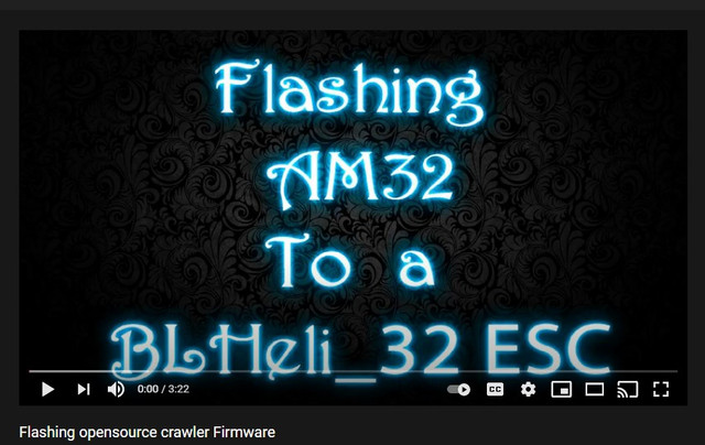
Basically you can skip some of the more complicated things and do it all with just the STM32CubeProgrammer with 4wires, and the flight controller using the receiver plug and a battery.
I am basically copying these instructions from my PDF file I shared earlier in a few places. I will try to keep this post updated but if not all the files in my google drive will be the most recent.
This motor HobbyStar 2820 (3542) Brushless Outrunner Motor 1450KV
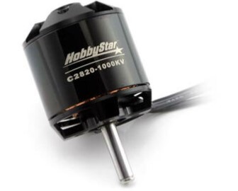
works pretty good, the big downside is the 5mm shaft. so you need a 5mm pinion.
Holmes Hobbies, and Team Brood both have a wide variety of outrunners with 1/8th pinion shafts but they cost quite a bit more too.
How to program a Airbot wraith32 35A v1 ESC to run the Holmes Hobbies Revolver 1400kv or 1000kv silently.
First off a huge credit goes out to AlkaM from https://www.rcgroups.com/forums/member.php?u=696658 who Designed this firmware, and continues to update and improve it. I am actually older firmware here because I can’t figure the new stuff out yet.
Also Thank You to those who posted in his forums who have preceded me: MadMax, MGeo, possibly others…
The main purpose of this tutorial is to run a Holmes Hobbies Revolver with out all that noise. Other outrunner motors will probably work fine as well. I have only tested this with the 1400kv stubby revolver, and I have heard the 1800kv or higher will suffer in performance. I don’t know why, something to do with loosing torque.
The firmware I am using at the time of writing this does not have the greatest drag brake. I think its just a setting I need to find but… I haven’t found it yet… I’m hoping some one else will make me a nice firmware.bin file I had a different esc earlier that preformed better from a different version of the same opensource firmware and it ran great IMO.
I will not be covering compiling the firmware in depth, but I am using AlkaM’s firmware from here https://github.com/AlkaMotors/AM32-MultiRotor-ESC-firmware and the target used for the wraith is MP6531. When you import it into STM32CubeIDE the project is called F051_II_bi_dir. That’s the quick version… That’s all you get…
Note, I have only tested this with the Airbot wraith32 35A v1, the Airbot wraith32 35A v1 and the 50A Airbot wraith32 Plus.
Step 1: Gather your supplies
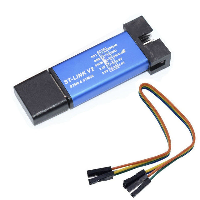
You’re going to need a table… and an esc (probably this specific ESC), and a ST-link v2 programmer with jumper wires, a BEC or BUCK converter (to power the servo and reciever), soldering Iron with a small tip, wires, non acid flux, and a Windows 10 computer.
Recommended optional supplies –a magnifying glass, or a good zoom for your camera (because this crap is tiny!) I use open camera (for android) because it doesn’t fall asleep.
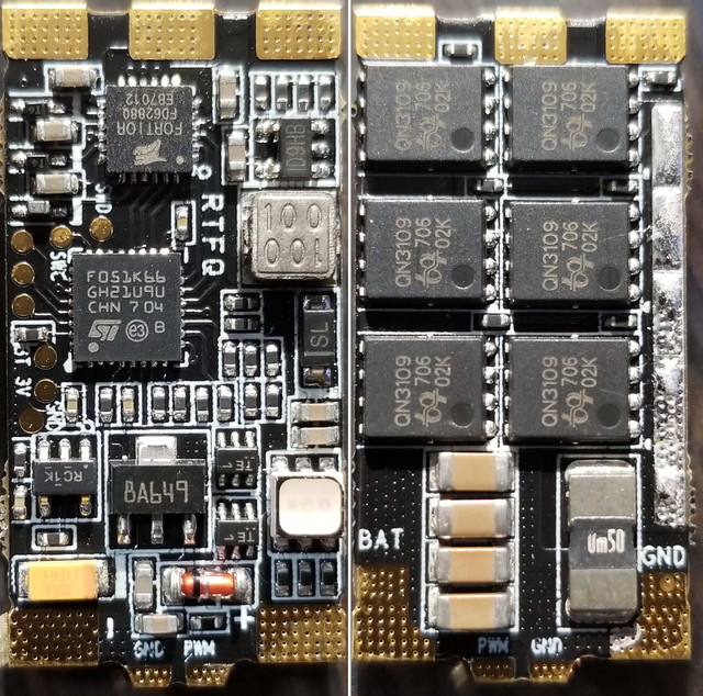
Step 2: Soldering- Part1
Solder Tiny wires to SWD (SWDIO), SWC (SWCLK), PWM, and - (GND, main negative power in for ESC).
Also Solder leads and a battery terminal to the (+POS - main positive power and - (- GND - main ground).
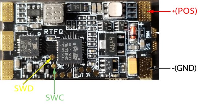
Tip: We need some tiny wire, I use stranded silicone 26awg wire. Its flexibility helps to keep it from tearing the tiny solder pads off.
Tip: An alternative to soldering wires to the SWD and SWC pads you can use pogo pins and just hold them in place by hand and use automatic mode when programming.
Note to self: consider updating this picture.
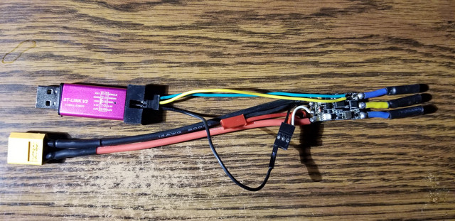
You Might as well solder the leads for the Motor and signal to the receiver now too.
Depending on how you do the wiring just make sure you send the power to the receiver without going through a bec first to lower the voltage, most receivers dont like 3s power.
Step 3: Download and install Software
STM32CubeProgrammer
Relatively straight forward, make sure you got your wires in the right locations.
3 wires connect to the ST-Link, SWD (SWDIO), SWC (SWCLK), and - (GND).
For power use your battery pack connected to the battery plug on the esc.
It is better to not use the power from the ST-Link as its too easy to kill the ST-links if you are not careful.
Check your wires again, seriously, just do it! Especially the power wire.
Connect the ST-Link to your computer.
(Removed) Step 5: Unlocking something w/ OpenOCD
I am not 100% sure this step is necessary but were doing it because we went through a lot of work installing the software for it already.
Turns out it wasn't necessary...
Step 6: STM32CubeProgrammer
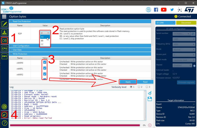
With your ESC and ST-Link connected open STM32CubeProgrammer and click the green connect button in the upper right corner.
1.Click on OB (Option bytes)
2.Select “Read Out Protection” and Set to AA
3.Select “Write Protection” and check all the empty boxes, scroll through, get them all and clickapply.
4.Now do a full chip memory erase
Oh I never told you to download the firmware.bin file… You also will need the interwebs, you probably have that if your made it this far, and the table is probably optional… Download the wraith_crawler_full_x.xx.bin file from (It is just a .bin file It could be called anything.bin) https://drive.google.com/drive/folders/1ggvkWlLNjDMoB1ryCYy4fE_xQ2l5m2cL?usp=sharing
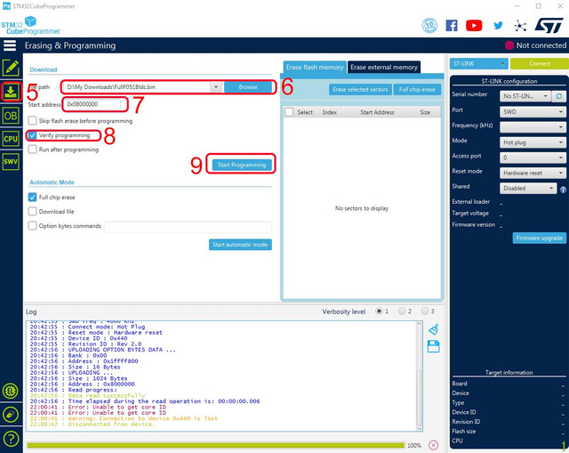
5.Select Erasing & Programming from the left
6.Browse for the firmware you just downloaded
7.Set the start address to 0x08000000 if it isn’t already
Info: if you have already uploaded a full file you can upload a part file at 0x08008000, the part files do not contain the bootloader. Part files are better uploaded from the configurator though.
8.Check the verify programming box if it isn’t already
9.And start programming (we are not going to do actual programming, were just loading some firmware, get a hold of yourself man!)
10.Unplug the ST-link from the esc and computer, Leaving it plugged in to the PC causes them to overheat.
Tip: You only need to upload the bootloader with the ST-link, these can be downloaded here too - Bootloaders - Next in the configurator you can upload the firmware and then click load default settings to install the EEPROM.
Step 7: Optional Testing
This probably shouldn’t be optional, but I don’t feel like explaining how to connect all your receivers, motors and batteries. I mean really if you made it this far, consider your self a pro! You can do this!
Step 8: Unsolder and Resolder
Unsolder all these wires and pins
As usual you need to solder the positive and negative battery leads on the 2 tab side.
The motor wires go to the 3 tab side (if the motor is going the wrong direction swap any 2 of these wires)
This esc was not designed to power a servo, so only run the ground and PWM to your receiver
Connect all this to your RC car
That’s about it…
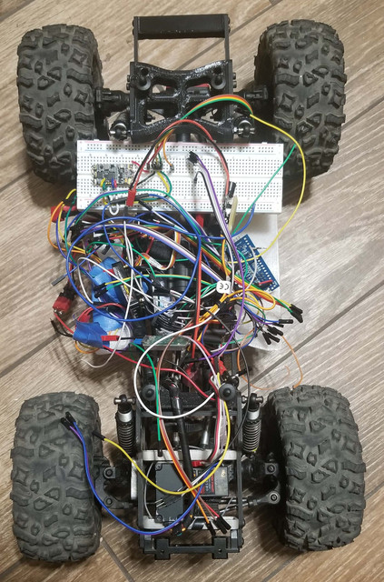
If everthing went acording to plan, you should end up with something that looks like this.
A different less Drunk tutorial can be found on Github here
Here is a video I made you can watch too, it also talks about using a flight controller to update and configure the firmware. It is where you would set your motor KV and change the startup power.
(At the moment it is outdated and shows using the power from the ST-link, Don't use power from the ST-link, they burn up too easy.)

Basically you can skip some of the more complicated things and do it all with just the STM32CubeProgrammer with 4wires, and the flight controller using the receiver plug and a battery.
I am basically copying these instructions from my PDF file I shared earlier in a few places. I will try to keep this post updated but if not all the files in my google drive will be the most recent.
This motor HobbyStar 2820 (3542) Brushless Outrunner Motor 1450KV

works pretty good, the big downside is the 5mm shaft. so you need a 5mm pinion.
Holmes Hobbies, and Team Brood both have a wide variety of outrunners with 1/8th pinion shafts but they cost quite a bit more too.
How to program a Airbot wraith32 35A v1 ESC to run the Holmes Hobbies Revolver 1400kv or 1000kv silently.
First off a huge credit goes out to AlkaM from https://www.rcgroups.com/forums/member.php?u=696658 who Designed this firmware, and continues to update and improve it. I am actually older firmware here because I can’t figure the new stuff out yet.
Also Thank You to those who posted in his forums who have preceded me: MadMax, MGeo, possibly others…
The main purpose of this tutorial is to run a Holmes Hobbies Revolver with out all that noise. Other outrunner motors will probably work fine as well. I have only tested this with the 1400kv stubby revolver, and I have heard the 1800kv or higher will suffer in performance. I don’t know why, something to do with loosing torque.
The firmware I am using at the time of writing this does not have the greatest drag brake. I think its just a setting I need to find but… I haven’t found it yet… I’m hoping some one else will make me a nice firmware.bin file I had a different esc earlier that preformed better from a different version of the same opensource firmware and it ran great IMO.
I will not be covering compiling the firmware in depth, but I am using AlkaM’s firmware from here https://github.com/AlkaMotors/AM32-MultiRotor-ESC-firmware and the target used for the wraith is MP6531. When you import it into STM32CubeIDE the project is called F051_II_bi_dir. That’s the quick version… That’s all you get…
Note, I have only tested this with the Airbot wraith32 35A v1, the Airbot wraith32 35A v1 and the 50A Airbot wraith32 Plus.
Step 1: Gather your supplies
You’re going to need a table… and an esc (probably this specific ESC), and a ST-link v2 programmer with jumper wires, a BEC or BUCK converter (to power the servo and reciever), soldering Iron with a small tip, wires, non acid flux, and a Windows 10 computer.
Recommended optional supplies –a magnifying glass, or a good zoom for your camera (because this crap is tiny!) I use open camera (for android) because it doesn’t fall asleep.


Step 2: Soldering- Part1
Solder Tiny wires to SWD (SWDIO), SWC (SWCLK), PWM, and - (GND, main negative power in for ESC).
Also Solder leads and a battery terminal to the (+POS - main positive power and - (- GND - main ground).

Tip: We need some tiny wire, I use stranded silicone 26awg wire. Its flexibility helps to keep it from tearing the tiny solder pads off.
Tip: An alternative to soldering wires to the SWD and SWC pads you can use pogo pins and just hold them in place by hand and use automatic mode when programming.
Note to self: consider updating this picture.

You Might as well solder the leads for the Motor and signal to the receiver now too.
Depending on how you do the wiring just make sure you send the power to the receiver without going through a bec first to lower the voltage, most receivers dont like 3s power.
Step 3: Download and install Software
STM32CubeProgrammer
We need this to disable write protection on the Option bytes, and to load the firmware. https://www.st.com/en/development-tools/stm32cubeprog.html#get-software
I think you need to register or something, but it's free, no credit card, just an annoyance.
Step 4: Connect ST-programmerI think you need to register or something, but it's free, no credit card, just an annoyance.
Relatively straight forward, make sure you got your wires in the right locations.
3 wires connect to the ST-Link, SWD (SWDIO), SWC (SWCLK), and - (GND).
For power use your battery pack connected to the battery plug on the esc.
It is better to not use the power from the ST-Link as its too easy to kill the ST-links if you are not careful.
Check your wires again, seriously, just do it! Especially the power wire.
Connect the ST-Link to your computer.
(Removed) Step 5: Unlocking something w/ OpenOCD
I am not 100% sure this step is necessary but were doing it because we went through a lot of work installing the software for it already.
Turns out it wasn't necessary...
Step 6: STM32CubeProgrammer
With your ESC and ST-Link connected open STM32CubeProgrammer and click the green connect button in the upper right corner.
1.Click on OB (Option bytes)
2.Select “Read Out Protection” and Set to AA
3.Select “Write Protection” and check all the empty boxes, scroll through, get them all and clickapply.
4.Now do a full chip memory erase

Oh I never told you to download the firmware.bin file… You also will need the interwebs, you probably have that if your made it this far, and the table is probably optional… Download the wraith_crawler_full_x.xx.bin file from (It is just a .bin file It could be called anything.bin) https://drive.google.com/drive/folders/1ggvkWlLNjDMoB1ryCYy4fE_xQ2l5m2cL?usp=sharing
5.Select Erasing & Programming from the left
6.Browse for the firmware you just downloaded
7.Set the start address to 0x08000000 if it isn’t already
Info: if you have already uploaded a full file you can upload a part file at 0x08008000, the part files do not contain the bootloader. Part files are better uploaded from the configurator though.
8.Check the verify programming box if it isn’t already
9.And start programming (we are not going to do actual programming, were just loading some firmware, get a hold of yourself man!)
10.Unplug the ST-link from the esc and computer, Leaving it plugged in to the PC causes them to overheat.

Tip: You only need to upload the bootloader with the ST-link, these can be downloaded here too - Bootloaders - Next in the configurator you can upload the firmware and then click load default settings to install the EEPROM.
Step 7: Optional Testing
This probably shouldn’t be optional, but I don’t feel like explaining how to connect all your receivers, motors and batteries. I mean really if you made it this far, consider your self a pro! You can do this!
Step 8: Unsolder and Resolder
Unsolder all these wires and pins
As usual you need to solder the positive and negative battery leads on the 2 tab side.
The motor wires go to the 3 tab side (if the motor is going the wrong direction swap any 2 of these wires)
This esc was not designed to power a servo, so only run the ground and PWM to your receiver
Connect all this to your RC car
That’s about it…
If everthing went acording to plan, you should end up with something that looks like this.

Last edited:


