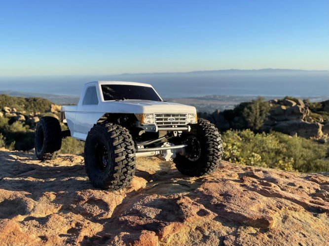
• Welcome to RCCrawler Forums.

    It looks like you're enjoying RCCrawler's Forums but haven't created an account yet. Why not take a minute to register for your own free account now? As a member you get free access to all of our forums and posts plus the ability to post your own messages, communicate directly with other members, and much more. Register now!

    Already a member? Login at the top of this page to stop seeing this message.

Project Mullet Has Officially Begun

DRED805

Rock Crawler
Joined
Mar 6, 2021
Messages
659
Location
Santa Barbara
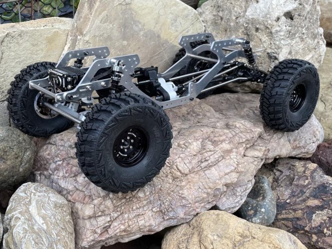
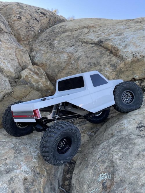
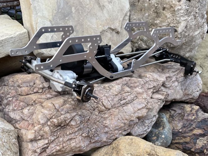
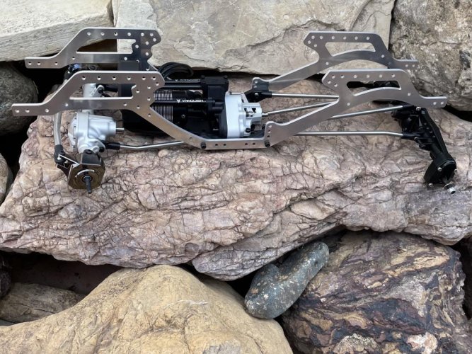
Business in the front, party in the back!


CURRENT PARTS LIST:

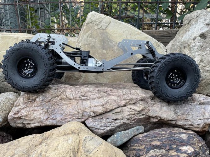
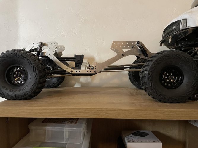
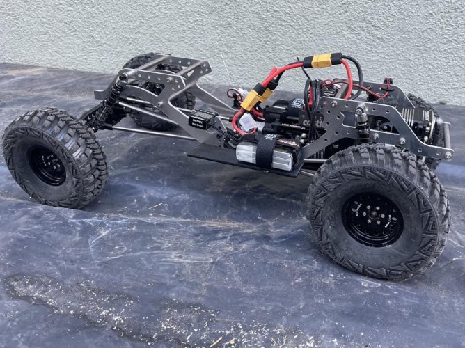
Brazin ATL V2 Flat Rail Aluminum Chassis
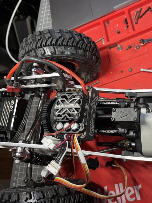
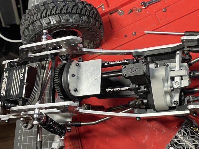
VFD Transmission (standard 6% OD)
VFD Dig
In The Works SCX10 III Gladiator 13.9" Wheelbase High Clearance Titanium Links
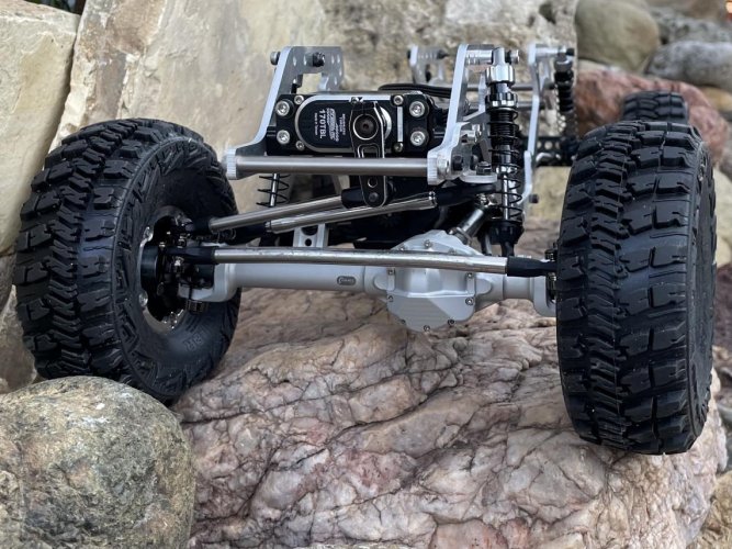
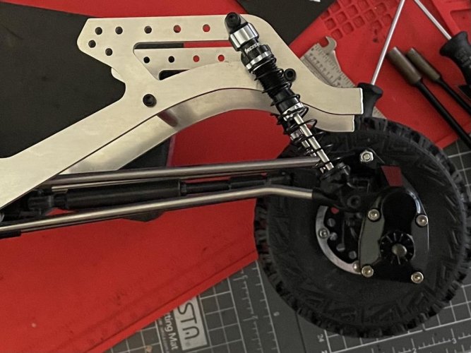
Vanquish F9 Pro Front Axle (vanquish underdrive diff gears)
SSD Heavy Knuckles (to help match rear weight)
KYX SCX10 III Metal Rear Axle (reverse cut diff gears, 14/21 OD portal gears)
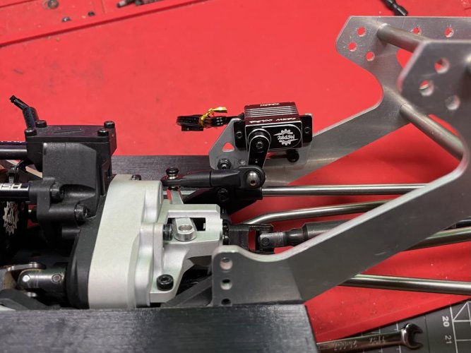
GSpeed LayDown Servo Mount
Protek 170TBL Servo
Brazin Aluminum Panhard Mount
RC4WD 67mm Titanium Links (chassis spacers)
Incision 90mm Shocks
SSD TRX-4/SCX10 II Kit Rear Driveshaft
Incision SCX10 II Front Driveshaft
Incision 1.9" Method MR307 Wheels
RC4WD 4.70"x1.87" Goodyear MT/R Tires
Crawler Innovations 4.50" Comp Cut Inner / Soft Outer Foams
Mamba X ESC
3Bros ACIS TEN 1600kv Motor
Spektrum SR315 Receiver
IERC Power Wagon Back Half Aluminum Sliders
NSDRC RS100 Micro Servo (dig)
Spare-Time Hobbies Hurtz Dig Compact Micro Shifter Mount
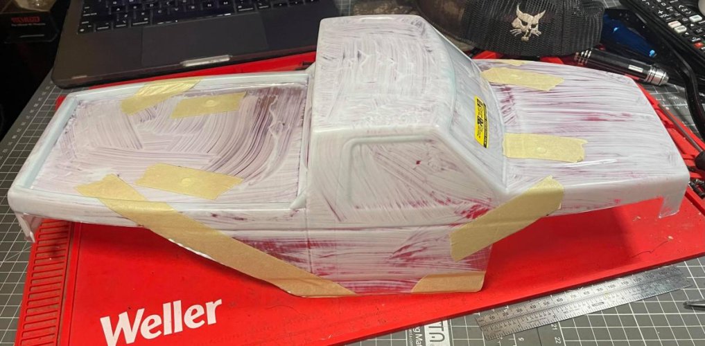
J Concepts Tucked F250 body
2x Tattu 850mah 3s Batteries (6s)


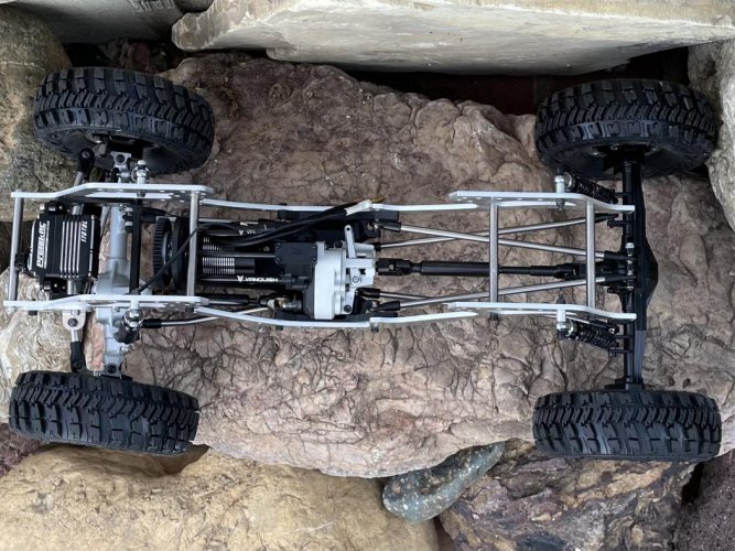
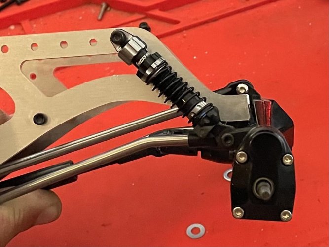
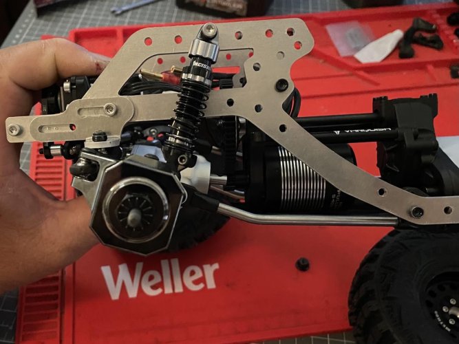
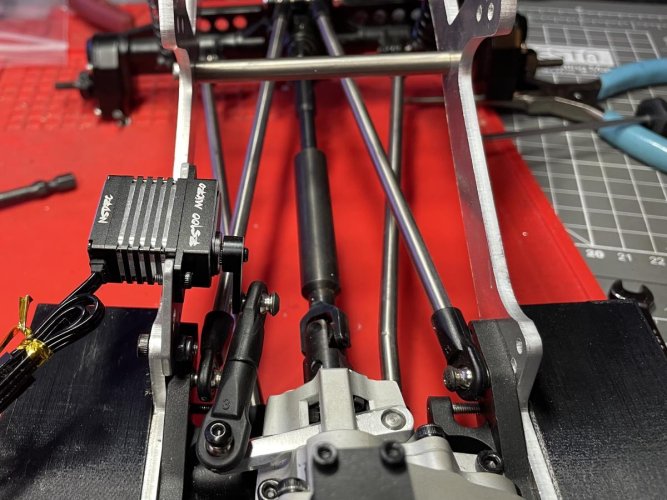
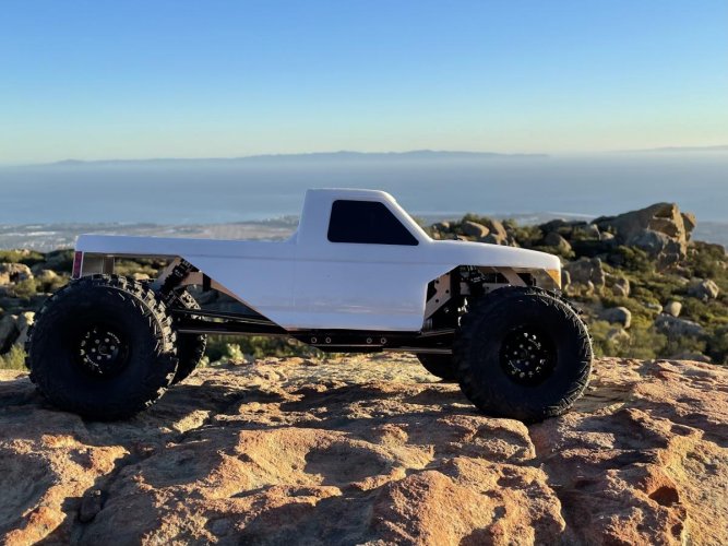
The rear links are comically long, but it'll be fun to see how it ends up. I went with a portal rear to help give them a little more clearance as well. It's definitely gonna take some tweaking to get the mishmash of parts to work together. For instance I need to lengthen the front upper link to get the right pinion angle, and clearance the skid plate so I can flip the lower links to the correct position while slammed. Getting the panhard worked out will be the next headache.

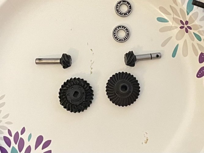
Gearing is a bit extreme as it sits. Even with the underdrive front diff and overdrive rear diff, the portal still puts it at roughly 48% overdrive overall. I already had those differentials for another vehicle, so I'm just gonna run them and see. If it's too much, I'll put one of the diffs to stock, and get the ssd portal overdrive gears to make it roughly 28% overdrive.

I've got pretty much all the parts to finish it, but I'm in no rush. I'll update the parts list as I go. Please feel free to give me any suggestions, or point out any issues I might be missing. Thanks for checking it out!
 

Attachments

  • IMG_7481.jpg
    IMG_7481.jpg
    182.9 KB · Views: 1,397
  • IMG_7482.jpg
    IMG_7482.jpg
    182.6 KB · Views: 1,376
Last edited:
I made some progress over the long holiday weekend.

Steering and panhard took a few hours of tinkering, but it tucks up real tight. I used a Gspeed laydown servo mount. In order to utilize existing holes in the chassis rails for the front holes in the mount, I had to have it slightly more forward than I originally wanted. I then had to drill and tap two new holes through the chassis and into the back of the mount to make it solid. To make the panhard parallel with the drag link, I had to slide the Brazin panhard mount as far forward as possible. I had to drill/tap another hole in the chassis for the front of that mount as well. Having the servo and panhard slid forward a bit actually worked out great, because the diff cover just barely slips up behind the panhard bar when completely stuffed. I'm happy with how everything lines up at full compression.

I used RC4WD 67mm titanium links as chassis spacers. Those, along with the Incision shocks and 170TBL servo, really match with the accidental silver/black theme this thing has. I'm not a fan of colorful stuff, so I guess those are the only colors that are leftover on a rig that's mostly metal.

The only real bummer so far is the rear end. When I flipped the diff to correct the wheel rotation, I realized I had to flip the output/pinion gear also. My high pinion rear end is now a low pinion rear end, which is frustrating. I wish reverse cut gears was a thing. The driveshaft is now slightly below the links near the axle, but it's not too terrible. I also had to cut the back of the chassis rails off to allow the rear end to fully tuck in, but that was expected.
 

Attachments

  • IMG_7503.jpg
    IMG_7503.jpg
    184.3 KB · Views: 1,274
  • IMG_7502.jpg
    IMG_7502.jpg
    180.3 KB · Views: 1,280
  • IMG_7501.jpg
    IMG_7501.jpg
    185.6 KB · Views: 1,283
  • IMG_7499.jpg
    IMG_7499.jpg
    184.5 KB · Views: 1,303
  • IMG_7495.jpg
    IMG_7495.jpg
    107.2 KB · Views: 1,297
  • IMG_7494.jpg
    IMG_7494.jpg
    116.1 KB · Views: 1,294
  • IMG_7493.jpg
    IMG_7493.jpg
    108 KB · Views: 1,304
Last edited:
I was wondering how you were going to address the rotation issue, that’s not too bad on where the driveshaft hangs down. Looks like it’s coming together, interested to see how you like it.

A quick google search turned up these results

https://www.boomracingrc.com/#horizontalTab1

https://deadloc-racing.myshopify.com/products/hardened-scx10-ii-reversed-diff-gears?variant=8114210046053

Thanks for the feedback. I found both of those, but neither would work for my application. The boom ones are only for their axles. On the deadlock Facebook page I read that they only work with ssd axles or something. I’d probably experiment with them if they were in stock.
 
Pasted from the description on boom racing’s site

Will fit:
Boom Racing BRX70/BRX90 PHAT Axle (Note: must be black color Third Member which fits reverse axle gear, red color Third Member will not fit)
AR44 style ring/pinion gear and locker with flipped diff feature

Will not fit
Stock AR44 axle housing

I believe the key here with both gear sets is that they won’t fit the stock axial ar44 housing. The ar44 housing does not have the clearance to fit the ring gear flipped to the opposite side. I don’t remember if the ar45 housing is the same way, or if there is more clearance on the diff cover. If there isn’t, there may possibly be with an after market diff cover.

Good call. I guess I misread it at first. I’ll look more into it when I get home from work. Thanks for the input!
 
I ordered the Boom Racing reverse cut gears on my lunch break, and then found these when I got home from work...

https://www.amazon.com/dp/B08GPWDZ5D?psc=1&ref=ppx_yo2_dt_b_product_details

I ordered them as well (2 days shipping!). They're not the greatest quality, but probably not any worse than boom racing. They went in fine, the driveshaft is up out of the way, and everything is working correctly. Thanks for not letting me give up on reverse cut gears, twade!

Unfortunately I had to get rid of the SSD overdrive diff gearing that was there, so I've gone from ~28 percent overdrive to ~38 percent overdrive overall. I have 14/21 portal OD gears in it, but I can go even further to 13/22 portal gears if it's too much. I'm really tired of buying gears, though... haha.
 

Attachments

  • IMG_7511.jpg
    IMG_7511.jpg
    85.9 KB · Views: 1,179
  • IMG_7512.jpg
    IMG_7512.jpg
    122.8 KB · Views: 1,183
Project Mullet should have been my nickname in the late 80s.

Digging this project.
 
Having to get a little creative with electronics mounting locations... haha.

Also, Thanks to Fricker08, I flipped the rear lower links around, so the bend is at the skid. I think it's gonna be much better that way.
 

Attachments

  • IMG_7540.jpg
    IMG_7540.jpg
    171.7 KB · Views: 1,126
  • IMG_7539.jpg
    IMG_7539.jpg
    168.5 KB · Views: 1,146
  • IMG_7531.jpg
    IMG_7531.jpg
    113.5 KB · Views: 1,081
Last edited:
Looking good man! Love your attention to detail.

Im going through the same stuff on my current build lol. Trial and error. I've also noticed how big of an impact just one little change in the link system does.
 
I haven't been working on this thing much recently, but I finally decided on how/where to mount a dig servo. Decided to go with an NSDRC RS100 micro servo. I had an extra hurts dig micro servo mount from STH, which worked great. I used an optional upper link mount on the chassis for one side of the servo mount, and then tapped a second hole for the mount right into the chassis rail. Seems good and solid.

I want to shorten up the link a few more mm because that tiny arm is a little too extended for my liking, when the dig lever is completely into the rear position. Any suggestions on a clean super-short link, besides just shaving a couple mm off each rod end?

I don't particularly like how it's hanging outside the chassis like that, but I've been mulling it over for weeks, and this is the best I can come up with. It'll be protected by the body and the GSpeed sliders (thanks Fricker08!), and it's so light it shouldn't throw off the balance much.

The truck is pretty much done now, but I'm getting held up on how I want to mount the body. My goal is to get that worked out this weekend, but we'll see.
 

Attachments

  • IMG_7643.jpg
    IMG_7643.jpg
    110.8 KB · Views: 1,059
  • IMG_7644.jpg
    IMG_7644.jpg
    153.9 KB · Views: 1,038
You could get away with using smaller hardware on your shift linkage. I'm thinking some ball studs/cups from a 1/18-1/24 car. I'm almost certain I have a new set from an RC18 around here, you're welcome to them.

Or, flip your servo so the output is toward the rear instead of the front, and use a longer link instead. That might be the better option since it means less angular change through its travel.

Nice. I might take you up on that. Or maybe I’ll rob some steering linkage off the yeti jr. that I have no plans of ever using again.

At first I had the servo flipped, but apparently I have some sort of OCD, because I couldn’t handle having the servo wire pointed towards the rear… haha.
 
Hey dred, just came across this thread. Good lookin build brother. Had a though on your dig servo. Wat if u moved the servo to the other side of the mount? That would almost put the link in more of a straight line n likely not trigger your ocd as much lol
 
Hey dred, just came across this thread. Good lookin build brother. Had a though on your dig servo. Wat if u moved the servo to the other side of the mount? That would almost put the link in more of a straight line n likely not trigger your ocd as much lol

Haha. I just trimmed the rod ends to shorten it up ~5mm and I'm good with it now. Thanks for the suggestion!
 
Only thing more tedious than watching paint dry is watching body mask dry. Hacked the **** out of the J Concepts Tucked F-250 body! Gonna have to take more off the front corners, but I'll do that after paint/stickers to see what looks least terrible.
 

Attachments

  • 248350534_1575978609404128_5389664116349176840_n.jpg
    248350534_1575978609404128_5389664116349176840_n.jpg
    107.6 KB · Views: 872
Took it out for it's maiden voyage after work today. I'm extremely happy with this truck. Obviously the long wheelbase causes some breakover issues, but the trade-off for how stable it is, is absolutely worth it. The extra axle clearance in the rear definitely helps. I can't believe the lines this thing was climbing. So stoked.

Didn't get many pics, because I was by myself and having too much fun.
 

Attachments

  • IMG_7704.jpg
    IMG_7704.jpg
    177.7 KB · Views: 852
  • IMG_7702.jpg
    IMG_7702.jpg
    165.9 KB · Views: 844
  • IMG_7696.jpg
    IMG_7696.jpg
    179 KB · Views: 842
Back
Top