• Welcome to RCCrawler Forums.

    It looks like you're enjoying RCCrawler's Forums but haven't created an account yet. Why not take a minute to register for your own free account now? As a member you get free access to all of our forums and posts plus the ability to post your own messages, communicate directly with other members, and much more. Register now!

    Already a member? Login at the top of this page to stop seeing this message.

brianw's portal Optic

brianw

RCC Vendor
Vendor
Joined
Jan 22, 2010
Messages
1,497
Location
WV
All I have is electronics and a "plan" at the moment.
  • HH 3500kv puller pro
  • Castle Copperhead
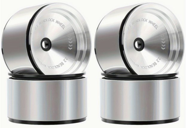
  • 2.2 wheels with 1.9 Tusks
  • Dlux Fab 80mm shocks
  • F10 Portal Axles
  • VFD Twin Transmission
I'm going to print another Knight Customs set (interior, engine, terra bug) but I have no idea what color scheme I'm going with. I have a black cage on it's way.

Screenshot 2025-04-07 093904.jpg
 
Last edited:
I'm also working on a Portal H10 Optic using the VS4-10 portal kit as a parts donor (plus a 2nd front axle for the rear). So far I'm not convinced its a great fit for he H10 optic as the portals raise the rig up 12mm and there isnt space for the portals to tuck up/into the cage when lowering it back down. But I'm still working on a few ideas to make it work.

I mocked up some Boss shocks with the offset mounts that drop the rig 12mm and the link mounts hit the cage in the rear limiting the travel of the shocks by 10mm (out of 22mm).

Next thing I'm going to mock up is a set of 80mm shocks to see if that can help with clearance and lower the rig.

All that said if you dont mind the rig being raised a bit this can totally work. It will also simplify it a ton if you use a rear portal axle in the rear and not a front axle.

I havent mocked up the transmission yet but I do plan to use the shorty conversion kit (because the servo wont clear without it). I also plan to use either a modified VFD skid or the VRD skid (just be aware the VRD uses a different mounting hole spacing and link lengths). I also ordered the servo mounts that Scale Metal Supplies makes to help make the VFDT more compact VFD Twin Servo Plates.

EDIT: only the VFD twin skid has the right bolt pattern and placement because the twin is wider at the transfer case.

One other thing to note if you try this and a 4WS setup, the rear axle wont have enough triangulation to keep the axle from moving side to side. It helps a fair bit if you outboard the rear upper links on the skid side (like the front axle). I may try designing a new piece that goes between the skid and cage that will outboard the links, provide a double shear and prevent those links from being hang up points.

I could post a few pics if anyone wants but I dont want to hijack the thread anymore than I already have.
 
Last edited:
I could post a few pics if anyone wants but I dont want to hijack the thread anymore than I already have.

Hijack away, won't hurt my feelings at all lol.

I plan to run the portal rear axle, I don't need/want rear steer and I was thinking desert lizards in full droop to try to bring it down a little. I haven't even begun to think about the skid or links yet. I'm not even 100% sure I'll use all of the functions of the twin...

I've been reading JMo's thread over on the other site - Optic-al Illusion - good info.
 
not much in the way of updates, but I did assemble the axles today and I hope to assemble the trans tomorrow. I ordered the VFD twin skid plate and decided on tires - 1.9 jconcepts Tusks; they're on order as well.

I still haven't decided on what body to run...thinking I may print the Poorigin hood and doors...maybe terra bug roof and rear engine covers? Teal or teal and purple? who knows...
 
Well I'm glad you didn't try using a VRD or regular VFD skid like I mentioned trying. The bolt pattern and placement is different so you really do need to use the VFD twin.

On this skid you still need to use the shorty conversion kit and cut a bit off the front of the skid so the servo clears. I heated up the front of the skid and bent it upward and then cut it. Although before bending it I laid out the front mount point that goes to the motor plate, its 24mm back from the stock hole and centered between the 2 fake socket heads.

DTlYoXs.jpg


1UBMcS0.jpg
 
Back
Top