• Welcome to RCCrawler Forums.

    It looks like you're enjoying RCCrawler's Forums but haven't created an account yet. Why not take a minute to register for your own free account now? As a member you get free access to all of our forums and posts plus the ability to post your own messages, communicate directly with other members, and much more. Register now!

    Already a member? Login at the top of this page to stop seeing this message.

89Industries' TWS Datsun 510 build

89Industries

Quarry Creeper
Joined
Dec 7, 2022
Messages
276
Location
(in the) Boulder(s)
Finally starting my build thread on my TWS CTS chassis, Datsun 510 build. The little feedback from people here wasn't great but the kit plus shipping was reasonable compared to the MST it is likely based on. Plus having worked with a lot of bicycle industry companies in Taiwan, someone leaving a company to start their own almost identical company is quite normal and pushes the industry forward. And only building something from the major companies gets boring. Delivery from Taiwan only took a 10-14 days.

Anyway...

Realism, pssht! People love Datsun 510s (1600s, Bluebirds) because they were fun to drive, affordable, 4 wheel independent suspension econoboxes. Datsun 510s did win the 1970 East Africa rally (before the 240z) so they have some offroad prowess but really they're know more for being Paul Newman's first race car and winning Trans-Am 2.5 class over the Alfa Romeos and BMWs of the time. Well, this isn't any of that as the chassis uses solid axles front and rear and the body will limit its ability as a trail vehicle or rock crawler.

Anyway, got this around Thanksgiving 2024.

pW2PA59.jpeg


Ordered it up after one of the first cold days here and knew I was going to need something for when it actually got cold. Funny enough that's just now happening.

Also, got some brass wheel hexes and extra links to make sure I could configure the front with a CMS and panhard bar. Weird part was the CMS link kit gives you enough links to also 3 link/panhard bar the rear. The kit itself comes with all the plastic parts to mount the panhard bars.

TWS also included some scale CB antennae as a thank you/gift. Not sure where I will use them but maybe on this.

Also ordered up the Pandora RC Datsun 510 drift body from Rolling Garage RC out of Sacramento (Sac-Town as it is known to my friends who were born and still live there).

This is the closest I have to a precut body picture
RzYUwgl.jpeg


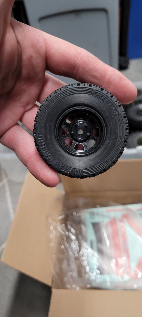
This picture does highlight probably the biggest limitation with using a drift body on a trail truck. Tire clearance. So I went tire and wheel shopping on Ebay and found some 78mm diameter tires on 1.55" rims. And then in a fit of indecision bought both appropriate sets of tires and 2 other sets of wheels and tires.

Top Left wheel and tire ended up going on the 510 for now. Kind of a BFG Krawler rip-off tread but the upper right reminds me more of an era appropriate tire and also a BFG rip-off. Bottom 2 tires are 3.75" OD BFG KM3 rip-offs. Pretty sure there is no licensing to use that name on the sidewall. Lower left set ended up on my newly built Tamiya BBX.
gHk1Xbl.jpeg
4nKBZk8.jpeg


To finish off collecting parts for this I had a used HW1080 g2 ESC, used Reedy 16t 5 slot motor from my sons Gatekeeper, a radiolink 6 channel rx, and a Amazon DS3235 Pro 35kg servo.

I'll start in on building the kit next post. Hopefully I took some pictures. I am not big on stopping to take a picture. Documentation has always been my nemesis.
 
Don't think I've ever seen a crawler built with a 510 body. I also never remember seeing a TWS build. Definitely interested in seeing this one progress and hearing your feedback on the rig. The TWS CJ is cool.
 
The traxxas 1.9 stock car wheels with the lettering removed look pretty good as a stock steelies with a huge sidewall. This is them on some 1.9 hpi pirelli rally tiresView attachment 509525
Those do look good and I like the Pirelli branding. They'd be era appropriate for sure.

BUT, the wheels I'm using in all the photos above are all 1.55" and the smaller tires have an OD of 76-78mm. Anything bigger will just cause more body/fender rub and I'm trying not to just cut out the fender all together. Trying to preserve some of the road going look.

I also really dislike tire rub so it's going to be a balancing act.
 
You could always heat the fenders just a little bit and add a flair to the wheel well. Just for a added little bit.

That's a cool idea. Honestly I'd be little scared of completely screwing up the body though. I had seen somebody replicate body damage using a bit of heat on a Lexan body and thought about doing that to mimic the car in the garage but also thought I'd likely mess it up.

Will have to try this on a easy to get body sometime. Or some scraps of lexan.

I did actually get the bolt on fender flares from Pandora but just don't really like the look of them, plus when I was considering using them it was just adding too much complexity at the moment. Still a bunch of stuff I need to figure out.
 
For full-on vintage BRE Datsun racing wheels, search for HPI MX60 4-spoke American Racing wheels, available in 2 offsets and Matte chrome, black, gunmetal, white (and maybe more?)...

There's also the old-school Mini-lite (aka Panasport) 8-spoke HPI wheels, Proline makes basically the same ones.

You could try stretching 1.55 tires over the plastic wheels,, too.
 
Let's keep going a bit.

So, just to note, I didn't buy this kit so that I could have perfectly followable directions to put something together. I bought it because it seemed adaptable to the wheelbase of the body I wanted to use and because it had some interesting stuff like the planetary transmission and floating motor to transmission mount. I knew I was going to need to figure stuff out so "perfect" instructions were not a requirement.You


Like any kit I've seen so far everything comes in bagged stages and sprues except that in the TWS CTS advanced kit case they pre-assembled the axles, transmission and transfer case. But of course I took stuff apart to make sure there was grease (there was some) and just to see how everything fit an worked.

Plus the advance kit comes with 3mm steel links and rod ends in addition to the plastic links. And I also purchased an additional set of steel links to make sure I had the links to use with a Chassis mounted servo rather than the kit's axle mounted servo. Many links were similar lengths so a little organizing and some trial and error was needed to get to the 257-260mm wheelbase the 510 body needs. Standard CTS wheelbases are 242,252 and 267mm.

So pretty much I just assembled things in the order I wanted and referred to the manual as needed.

The skid plate attaches to the chassis rails using some steel nuts inserted into slots on the skid. Good solid joint that I am not concerned will strip out so that's good.
7fRwis7.jpeg


Chassis rails are plastic but for the purposes of this rig that is just fine. Things certainly stiffen up quite a bit after bolting in all cross members.

Obviously I skip a few steps in pictures but here's the motor, transmission and transfer case mounted into the skid and rails (after disassembly and greasing). You can see the shorty fixed length driveshaft connecting the trans to the transfer case. To either side are the "motor mounts". The motor does also bolt to the cross member that is peeking out under the motor and transmission. So really the motor mounts just make up for tolerances.
1iZzW15.jpeg

xE1wDq8.jpeg

A0gyF4J.jpeg


First guess where the shock towers go and some side platforms for electronics.
IzwfMrl.jpeg


I think I build the shocks at this point. Aluminum bodies, non-threaded preload (includes clip in spacers), plastic bearing housing and top cap. Pretty standard 2 e-clips and a piston shafts. Nothing too exciting or disappointing and they haven't started dripping oil yet.
bcqIvpF.jpeg

They come with a nice plastic spring seat for the body side which you should install before the rod end on the shock shaft. Doh. They also come with a small hex tool in the sprue to tighten the seal head (tool can be seen in picture above).
ifKYAV2.jpeg

Nice scale looking 70mm (eye to eye) shocks. Less friction than Traxxas GTS shocks but still noticeable. Hopefully it translates to no leaks down the road. Just a mm or so of preload on the spring without preload spacers. So no rattling springs, etc.
Ol8jwOK.jpeg


Plastic balls for the shocks are snug with minimal play or excess friction. Honestly, they fit better than many of the big name brands.


Then I installed the battery tray parts. Battery is rear mounted and the tray is 2 parts. I only use 96mm long shorty batteries in this type vehicle. The instructions and parts are made to run a full size 125mm or so long battery pack but I moved stuff around and got a pretty good set up for the 96mm long shorty packs and moved the placement as far forward as possible.
0waIg1K.jpeg


There is another of those plastic straps that fits onto the front part of the tray. I can slide the battery wires under the one show in the photo and then clip the battery in place with the front clip. Its on the tight side and I think a velcro strap would be easier and an easy way to control the battery wires as well. We'll see.

Well, that's the boring stuff done. Slightly more exciting stuff next update. Which since its supposed to be a high of 12 degrees F and I have a cold will probably be later today.
 
Now for the ever so slightly more interesting part.

Between the kit and the extra set of links I ordered, I had about 16 links to sort and figure out where to put them. Plus figuring out the CMS and panhard bar and steering links on the front.

Interestingly, the kit came with plastic heim joint balls but the CMS link kit came with steel balls, enough to do all the links for suspension and steering.

Axles after greasing
CERDXZX.jpeg


Links installed on axles.
OHFniFk.jpeg


Then install link mounts on the chassis and attach links. You can see how there are 2 possible mounting locations on the chassis for the front and rear links.
YLrMR2d.jpeg


Once the links were installed (4 link rear, 3 link front), I installed the servo to the mounts and then onto the frame rail. Then added the frame end panhard bar mount. (not great pictures, let me know if you have questions).Then installed the panhard bar and steering links.
OroSDm9.jpeg


Then bolted up the shocks, slapped some wheels and tires on it, put the HW1080 on the far side tray and the rx on the near side tray and did a preliminary wiring.
dfIAyU9.jpeg


At this point it was time to start fitting the body and adjusting link position and lengths and figuring out any other hang ups trying to fit the 510 drift body on to a crawler chassis, but I'll get to that in the next post.
 
Fitting the body. This is proving to be the most difficult part. Both because the body is designed for drift cars with smaller wheels and less suspension travel and also because its cold outside and it takes some effort to work in a cold garage.

Anyway, first fitting after cutting out most of the body just to see what's going on.
dOsVbxN.jpeg


Note that the rear shock towers line up at the rear of the passenger compartment. Fronts are under the hood.
RzYUwgl.jpeg


After a bunch of fiddling I learned that I wanted the body to mount lower than it is able to with the current motor and shock towers. I'd like to get the tires to be close to the top of the fender well when the vehicle is flexed and thus needing to go lower.

The shock towers had 2 mounting positions and I normally always use the upper hole, lowering the vehicle. So I decided I could actually use the lower hole and cut off the tops of the shock towers and figure out ride height some other way.

But that meant that the interference with the hood was now the 540 motor. So in went a Holmes Hobbies Revolver 380 2000kv brushless motor and Castle Creations Mamba Micro X2. The HH revolver 380 is 30mm diameter where it mounts to the motor plate and slightly smaller as it goes forward in the car. The 540 motor is 36mm in diameter. And the HH Revolver 380 has the 25mm BCD 540 mounting pattern in it so it fit without issue.
hiNmi3W.jpeg
EpPXA1E.jpeg


I put a couple pieces of stick on foam on the tops of the towers for the body to rest on during mock up. I don't want mounting posts through the body as would be normal, so mounting the body is kind of where I am stuck at the moment.

I plan to make the bumpers out of steel and integrate the body mounting into that somehow.

This also my first time dealing with a lexan body that was molded in separate pieces and needs to be glued or screwed together. I tried taping up the different parts to make the body but then able to be separated to paint before final gluing.
Psh8qNQ.jpeg


Kind of worked but needed better so I made little "nuts" out of some old sprues and used M1.2 screws I ordered for doing possible bolt on fender flares to hold it all together yet able to take it apart for paint.
3FX7tNR.jpeg


I don't like bolt on fender flares on real cars so they were a "just in case" option for this if it really helped make tire clearance work. I don't think they will help so I won't use them.

Here's where I got to with the body location.
Lfy0sDc.jpeg


Rear wheels clear throughout travel pretty well. Not a lot of mud room but this will be a fair weather driver. The front needs clearance. Even without the steering the front needs work but with steering it will need more. I like doing this part with a sanding drum on a dremel and doing a little at a time. But with a cold garage, this will have to wait.

Also, note the rear overhang. Not exactly the best departure angle.

I also started making paper dolls for a steel skid plate and sliders. I'll cut these parts out of some 1mm thick-ish steel sheet, weld together and where you see the 2 small square holes, will slide 3/16" square or round rod through which will extend out to the slider. Then tack a thin sheet of steel to that. Hopefully it will make a nice smooth bottom to slide over stuff. The CTS chassis as it is stock looks like it would have a few hang up spots where the lower links mount and where the transfer case pokes out the bottom slightly.
xdqxdub.jpeg


And started working on the front bumper mount. I am thinking I will put a hinge in front bumper, attach the front grille of the body to that and then somehow use the rear bumper as the rear latch, allowing the body to swing up (like a Vanquish Phoenix).

The body of the 510 has 2 air ducts immediately behind the front bumper. I plan to open those on the body and run the bumper parts through there. And finally using the lexan front bumper over a steel bumper.

LNqjk3s.jpeg
nB9vKok.jpeg


Unfortunately, the rear of the 510 has no such actual openings and the rear bumper just mounts to the body sheet metal. I will need to figure that out. I had thought of using the rear bumper like a pin that slid through 2 holes in the body and into a mount on the frame that then gets a cross pin to hold it on. So pull 2 pins, pull bumper out and body pivots up. But Lexan is pretty thin in that area and I am thinking its not robust design to let the body just ride on 2 steel rods through holes. Might be able to attach a couple of flanged bushings to the lexan either with some glue or those same tiny m1.2 screws. The heads would get hidden behind the bumper a bit. Again, I plan on using the lexan bumper form over the steel rear bumper.

That's where I am at currently. So let's see how motivation and garage temperatures go over the next few months.
 
Oh, for those wondering about the TWS kit and running. I haven't taken it out side yet but have driven it around the basement without the body.

The drivetrain is quite smooth once I got the pinion/spur mesh correct.

The final drive ratio is pretty low. With the included 20t pinion the FDR is still 49.99 meaning that with the 2000kv motor on 3s and tiny 78mm od tires I expect it to top out at 4.38 mph. The motor and transmission will accept up to a 25t pinion which would give me a FDR of 40 and top speed of 5.5mph which is pretty close to where I run my trail trucks. But honestly I have no idea what to expect to need or want with such small tires. Luckily the pinion is quite easy to access and change.

It does use a .6 MOD pinion in case you are wondering. So now I have a selection of .6 pinions waiting to be tried out.

I also plan to do inner fenders and an interior with driver, but lots of stuff to figure out and make/do before I even think about that stuff.
 
Back
Top