new2rocks
I wanna be Dave
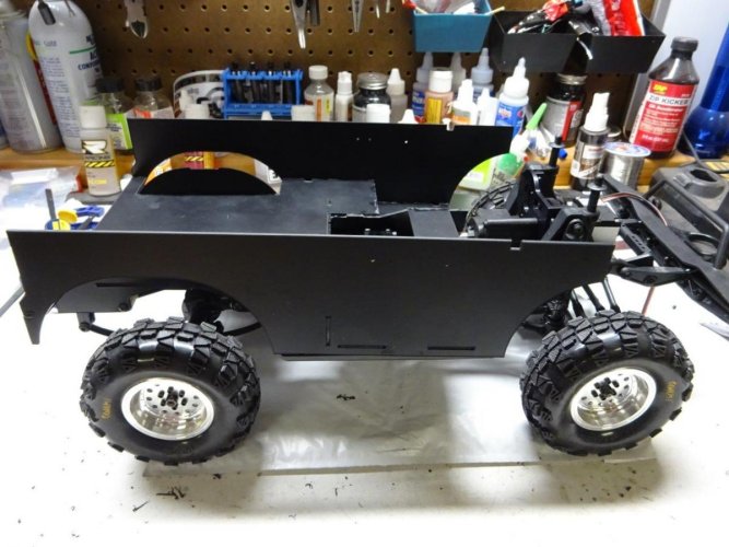
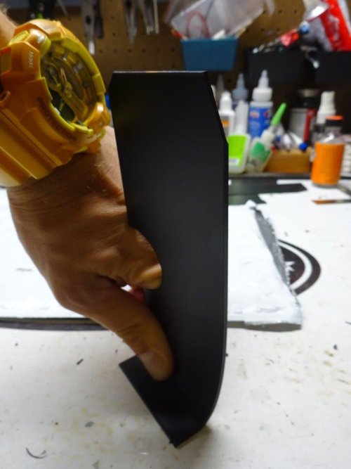
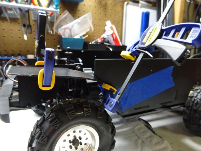
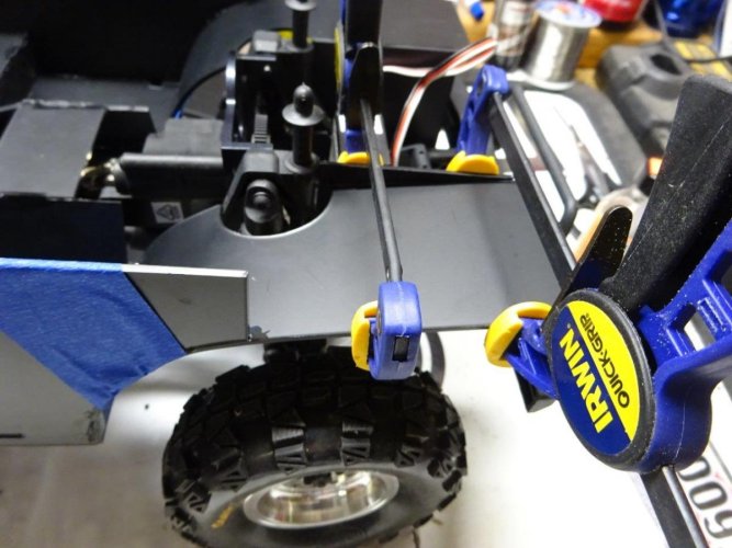
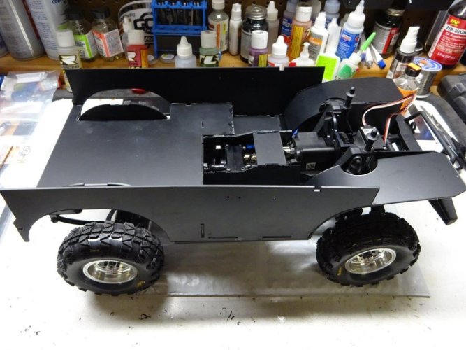
GCM has created an ingenious new interior kit for the Ascender Bronco, so I was naturally very excited to get ahold of one. GCM has done an amazing job of designing this kit to take advantage of every cubic inch of space inside the Vaterra Bronco body with an incredibly strong and versatile package. "thumbsup" to our friends in Canada for this one!
Before installing the interior kit, you'll need to do a forward motor conversion and eliminate the rear shock hoops through a rear leaf conversion or a rear shock relocation kit. Check out our Bronco anniversary celebration build thread for details on those mods:
http://www.rccrawler.com/forum/vaterra-ascender/562532-new2rocks-roo-celebrate-bronco.html
If you haven’t worked with styrene before, I highly recommend having the following tools and supplies handy:
- a good hobby knife
- Plastruct Bondene, Plastruct Plastic Weld or similar plastic adhesive
- CA glue
- Shoe Goo or E6000
- sandpaper of varying grits (I usually go from 320 up to 1000)
- a set of hobby files
- clothespins and/or appropriately sized clamps
The interior kit does not come with a steering wheel, steering column, shifters, door handles, window cranks and seats. But no worries, as everything but the seats is conveniently available on Axial parts tree AX80037. There are also numerous options for seats to suit your tastes.
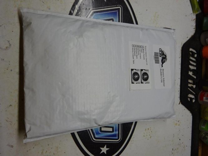
So let’s get started. The package looks innocent enough:
And then you see this:
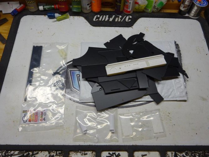
Holy pile of parts, Batman! I’m getting flashbacks to the Beast build. But fear not…this actually goes together quite easily, as you’ll see. If you want to lay out all of the parts and sort them before you start, you can. But there’s no need. Just follow me…
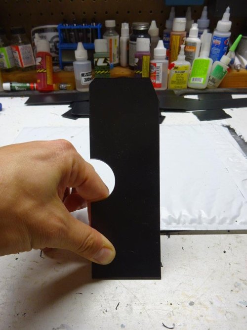
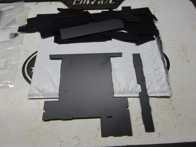
1. Let’s start with the main floor pan. It’s easy to spot in the pile of styrene pieces, because it’s the biggest part. Then find the long, skinny riser pictured next to the floor pan (also easy, as it’s the only piece that has anything close to that shape):
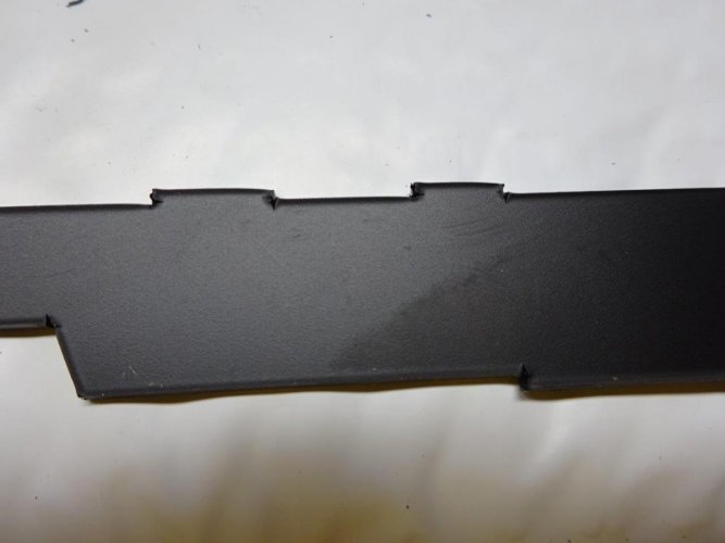
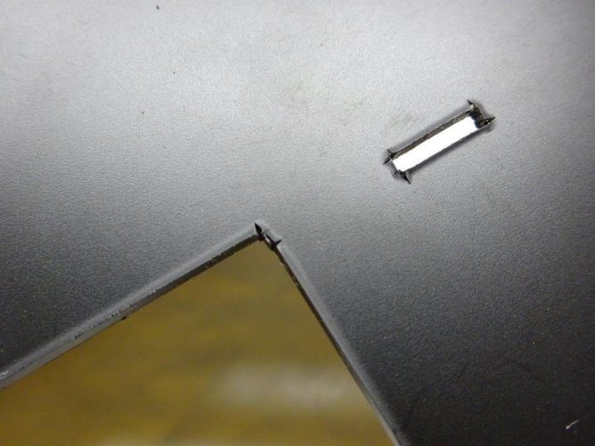
2. Take a careful look at both sides of the tabs and slots on these pieces. You’ll see that the cutting process produces some lips that tend to be more pronounced on one side than the other. At each step along the way, test fit the pieces and trim/sand tabs and slots before trying to glue them. Some pieces may need a bit more trimming than others, so test first and them trim/sand a little bit at a time until you get a nice snug fit.
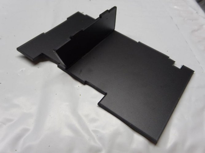
3. Glue the riser to the floor pan at a 90-degree angle

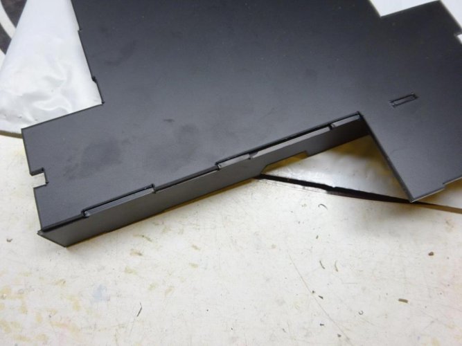

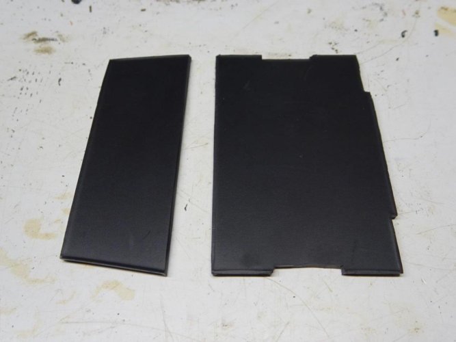
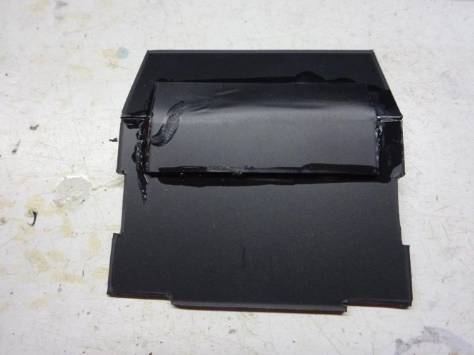
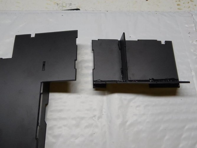
4. Locate the two floor sections that form the base of the front seat foot wells. I recommend starting with the left (driver’s) side, which has a slot in the middle. Locate the small riser for the driver’s side foot well, also pictured below, and glue them at a 90-degree angle. Note that the angled side of the riser will go on the side of the floor pan that has the cutout and tab.


5. Locate the two sides of the center driveshaft tunnel. These two parts are identical, so pick either one. Glue it in place against the angled side of the driver side foot well riser and along the side of the driver side floor pan.


6. Glue driver side footwell assembly to the main floor pan and riser as shown.
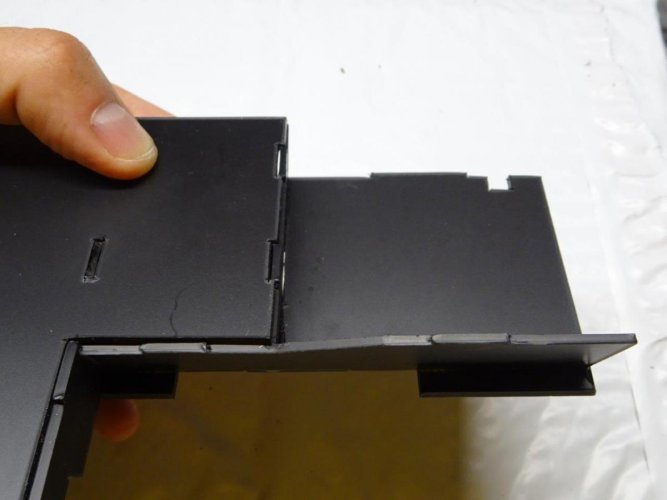
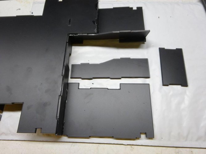
7. Glue passenger side footwell floor pan to the main floor pan assembly.

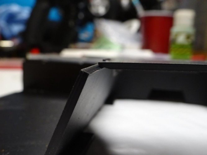
8. Take the other side of the driveshaft tunnel and locate the top of the driveshaft tunnel. I recommend using a hobby knife, sandpaper or file to bevel the sides of the top piece for a tighter fit against the top edges of the center tunnel sides. Glue the right (passenger side) of the tunnel and top of the tunnel at the same time, using the top of the tunnel to help set the proper angle of the right side of the tunnel.

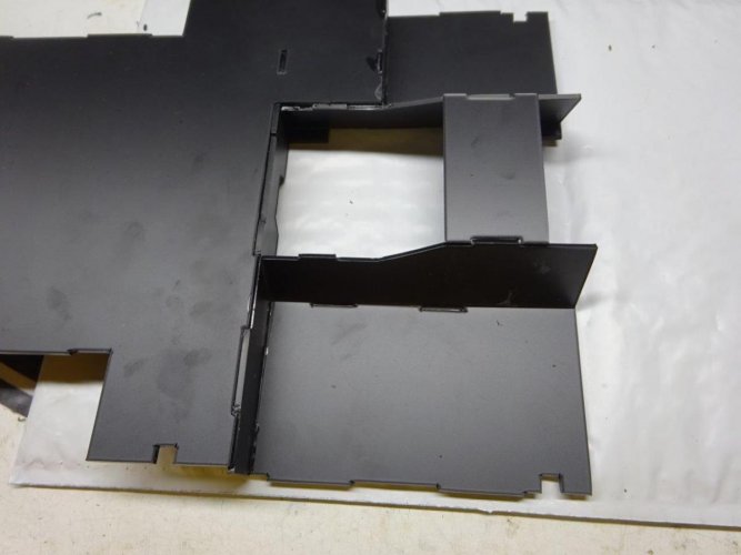
And with that, your floor pan is nearly complete. It should look like this from above:
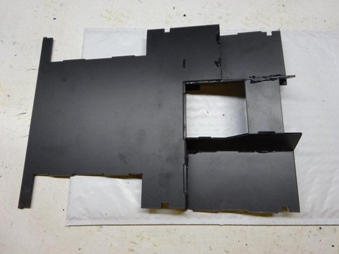
And from below:

9. With the floor pan nearly complete, this is a good time to reinforce the undersides of all the joints by adding a bead of Shoe Goo or E6000. If you're using Shoe Goo, try using a plastic syringe to apply so that you can get a nice thin bead. The tip on the E6000 tube is just the right size as is.
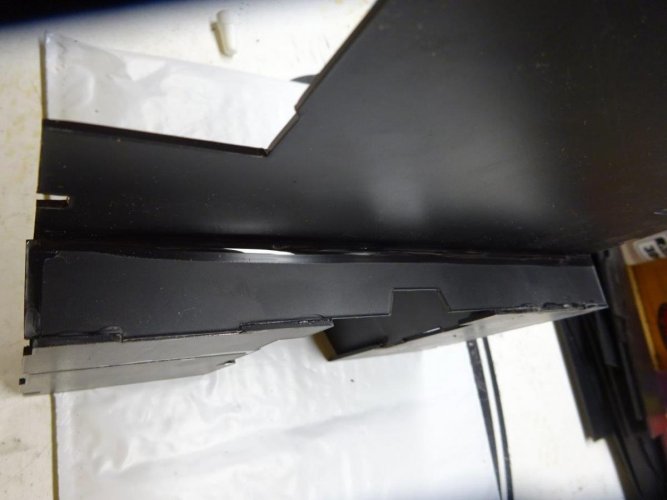
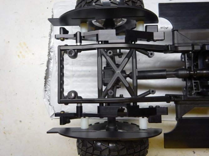
10. To prepare for mounting the floor pan and installing the wheel wells, trim off the floating battery tray mounts at the front of the slider brackets.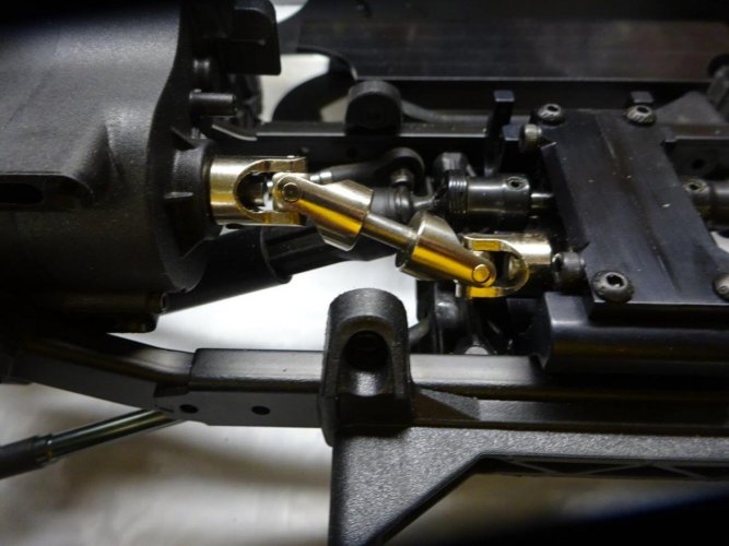
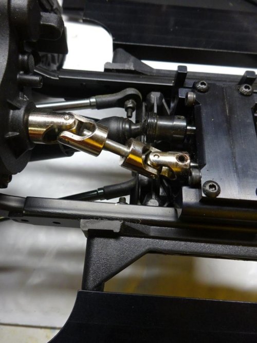
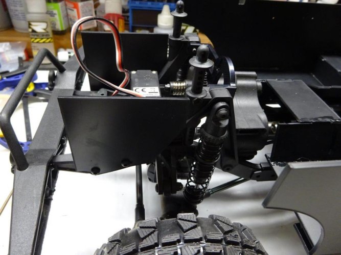
You will also need to remove the ESC and receiver box from the stock location to make room for the floor pan. Don’t worry, there will be plenty of room for the electronics in other places when you’re done.
Next up will be mounting the floor pan to the chassis, installing the wheel wells and sides of the tub, adding styrene bar reinforcements, and then finishing it off with the details.
Before installing the interior kit, you'll need to do a forward motor conversion and eliminate the rear shock hoops through a rear leaf conversion or a rear shock relocation kit. Check out our Bronco anniversary celebration build thread for details on those mods:
http://www.rccrawler.com/forum/vaterra-ascender/562532-new2rocks-roo-celebrate-bronco.html
If you haven’t worked with styrene before, I highly recommend having the following tools and supplies handy:
- a good hobby knife
- Plastruct Bondene, Plastruct Plastic Weld or similar plastic adhesive
- CA glue
- Shoe Goo or E6000
- sandpaper of varying grits (I usually go from 320 up to 1000)
- a set of hobby files
- clothespins and/or appropriately sized clamps
The interior kit does not come with a steering wheel, steering column, shifters, door handles, window cranks and seats. But no worries, as everything but the seats is conveniently available on Axial parts tree AX80037. There are also numerous options for seats to suit your tastes.
So let’s get started. The package looks innocent enough:

And then you see this:

Holy pile of parts, Batman! I’m getting flashbacks to the Beast build. But fear not…this actually goes together quite easily, as you’ll see. If you want to lay out all of the parts and sort them before you start, you can. But there’s no need. Just follow me…
1. Let’s start with the main floor pan. It’s easy to spot in the pile of styrene pieces, because it’s the biggest part. Then find the long, skinny riser pictured next to the floor pan (also easy, as it’s the only piece that has anything close to that shape):

2. Take a careful look at both sides of the tabs and slots on these pieces. You’ll see that the cutting process produces some lips that tend to be more pronounced on one side than the other. At each step along the way, test fit the pieces and trim/sand tabs and slots before trying to glue them. Some pieces may need a bit more trimming than others, so test first and them trim/sand a little bit at a time until you get a nice snug fit.


3. Glue the riser to the floor pan at a 90-degree angle


4. Locate the two floor sections that form the base of the front seat foot wells. I recommend starting with the left (driver’s) side, which has a slot in the middle. Locate the small riser for the driver’s side foot well, also pictured below, and glue them at a 90-degree angle. Note that the angled side of the riser will go on the side of the floor pan that has the cutout and tab.


5. Locate the two sides of the center driveshaft tunnel. These two parts are identical, so pick either one. Glue it in place against the angled side of the driver side foot well riser and along the side of the driver side floor pan.


6. Glue driver side footwell assembly to the main floor pan and riser as shown.


7. Glue passenger side footwell floor pan to the main floor pan assembly.

8. Take the other side of the driveshaft tunnel and locate the top of the driveshaft tunnel. I recommend using a hobby knife, sandpaper or file to bevel the sides of the top piece for a tighter fit against the top edges of the center tunnel sides. Glue the right (passenger side) of the tunnel and top of the tunnel at the same time, using the top of the tunnel to help set the proper angle of the right side of the tunnel.


And with that, your floor pan is nearly complete. It should look like this from above:

And from below:

9. With the floor pan nearly complete, this is a good time to reinforce the undersides of all the joints by adding a bead of Shoe Goo or E6000. If you're using Shoe Goo, try using a plastic syringe to apply so that you can get a nice thin bead. The tip on the E6000 tube is just the right size as is.

10. To prepare for mounting the floor pan and installing the wheel wells, trim off the floating battery tray mounts at the front of the slider brackets.


You will also need to remove the ESC and receiver box from the stock location to make room for the floor pan. Don’t worry, there will be plenty of room for the electronics in other places when you’re done.
Next up will be mounting the floor pan to the chassis, installing the wheel wells and sides of the tub, adding styrene bar reinforcements, and then finishing it off with the details.
Last edited:

