Hey everyone,
Welcome to my build tread
(hopefully by creating a tread it would keep me motivated enough to finish the project)
I started brainstorming what i wanted from this unimog which were
1. must have space for full interior and engine bay
2. doors and hood must open
4. it must look as realistic as possible
5. all mounting systems must be hidden from view
6. must hold full size battery pack
after blocking out the initial shape in a cad software i realized i had major issues:
1. dingo wheel base is too short
2. the cab needs to move forward to give motor space.
3. the battery and electronics needs to be re arranged if full interior space was to be achieved.
so before even starting on the body i had to create:
1. a bracket to relocate servo to chassis for realism, yet be low profile enough to have full engine bay and interior space.
2. with the above cms i will require a pan hard system to remove bump steer.
3. the battery and electronics will need to be hidden but not compromise space from engine bay and interior.
after looking online to see what others have done for cms + panhard
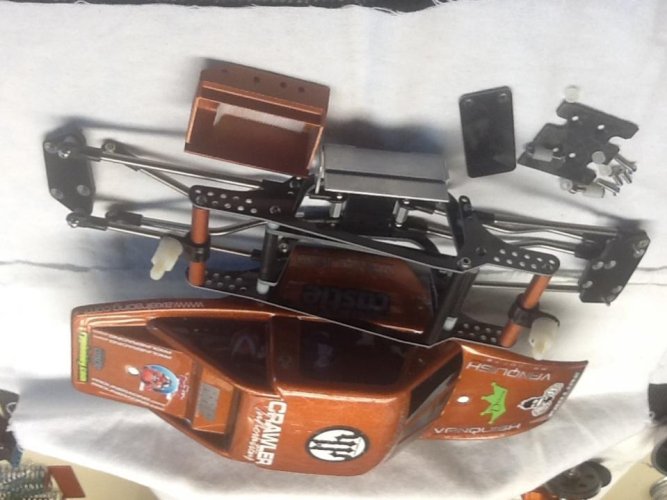
i came up with this, its not original concepts but its heavily modified to over come 3D printing weaknesses and limitations and pan hard tweaked for 0% bump steer and positive camber. it currently has the same amount of flex as a rtr scx10 in the front.
heres a picture of the cms + panhard

and heres a link to the video
IMG_1121_zps0jcpssiv.mp4 Video by Jacz_Loewen_Yang | Photobucket
hmm this post is taking to long =/
ill just show pics of where im at with this project.
interior area

engine bay area + body mounts

body mount bracket test

all structural parts done ready for test print.

first piece printed and fitted


let me know what you guys think =]
Welcome to my build tread
(hopefully by creating a tread it would keep me motivated enough to finish the project)
I started brainstorming what i wanted from this unimog which were
1. must have space for full interior and engine bay
2. doors and hood must open
4. it must look as realistic as possible
5. all mounting systems must be hidden from view
6. must hold full size battery pack
after blocking out the initial shape in a cad software i realized i had major issues:
1. dingo wheel base is too short
2. the cab needs to move forward to give motor space.
3. the battery and electronics needs to be re arranged if full interior space was to be achieved.
so before even starting on the body i had to create:
1. a bracket to relocate servo to chassis for realism, yet be low profile enough to have full engine bay and interior space.
2. with the above cms i will require a pan hard system to remove bump steer.
3. the battery and electronics will need to be hidden but not compromise space from engine bay and interior.
after looking online to see what others have done for cms + panhard
i came up with this, its not original concepts but its heavily modified to over come 3D printing weaknesses and limitations and pan hard tweaked for 0% bump steer and positive camber. it currently has the same amount of flex as a rtr scx10 in the front.
heres a picture of the cms + panhard
and heres a link to the video
IMG_1121_zps0jcpssiv.mp4 Video by Jacz_Loewen_Yang | Photobucket
hmm this post is taking to long =/
ill just show pics of where im at with this project.
interior area
engine bay area + body mounts
body mount bracket test
all structural parts done ready for test print.
first piece printed and fitted
let me know what you guys think =]