
 
|
MX-3 Independent Rear Steering Setup
by Jay Kopycinski (Copyright 2006) 9/22/06
I had been using a modified Traxxas TQ3 radio for a few years, but found that sometimes it glitched, or behaved oddly. I decided to step up to a FM radio and someone mentioned the Airtronics MX-3 as a possibility. The MX-3 is a 3-channel pistol grip radio with some nice tuneability features, including end point adjustment (EPA) for the servos. The 3 rd channel is setup for shifting so uses a two position switch.
I wanted to setup the 3 rd channel for independent rear steer on my crawler. So follow along and I'll show you how I did the mods.
(click any of the images to see them fullsize)
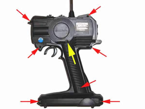
| Remove the seven sheet metal type screws on the back of the radio case. (There are three different lengths longest goes at the rear position where your hand grabs the grip, three shortest go in the other positions at top of radio, three middle length go at bottom of radio). I suggest you don't remove the eighth screw (yellow arrow) until you open the radio case. Separate the two case halves, being careful not to pull too hard on the wires that connect the two. You can now see how the eighth screw holds the throttle trigger. Removing it will allow you to detach the trigger and set the back half of the case aside. |
 |
|
Disconnect the battery tray harness and set aside.
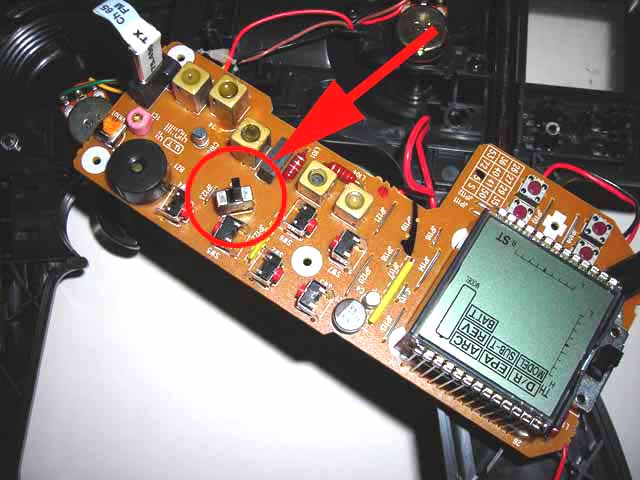
Carefully wiggle the circuit board off the little plastic posts and locate the board mounted shifter switch as shown here.
|
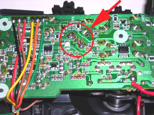
Remove the switch from the circuit board. I used a small tipped soldering iron and some solder wick being careful not to spread solder to adjacent traces or apply too much heat to the board. There are five soldered contacts. The outer two are used to mechanically secure the switch to the board. The center contact is the switched output' that runs to the integrated circuit. The remaining two are the switch inputs'. See the schematic below. |
|
|
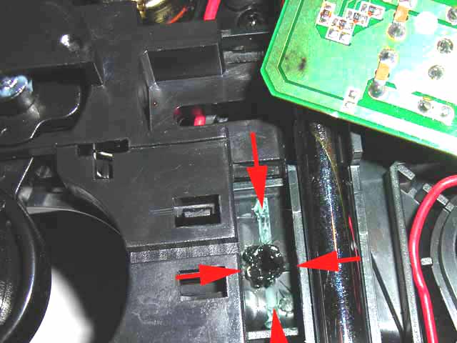
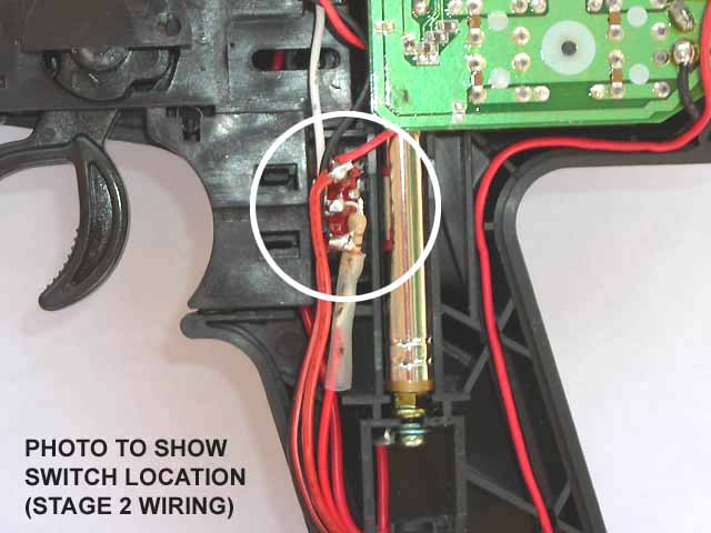
Unlike the TQ3, there's not a lot of room in the MX-3 to stuff the added toggle switch. However, it will fit vertically right behind the trigger assembly. You'll need to remove the internal plastic webbing in this area of the radio case. I tore it out with some needle nose pliers and cleaned up the area with a hobby knife.
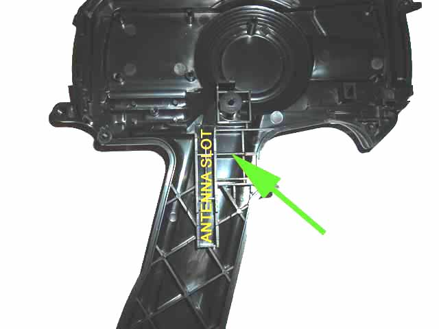
I then took my hot soldering iron and melted a small pilot hole from inside the radio case to set the switch position. I drilled the hole to the size needed and installed the toggle switch. You'll also need to remove some of the webbing on the back half of the radio case to accommodate the switch. See green arrow in photo below. |
|
|
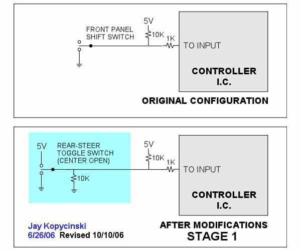
The original shift switch (two-position switch) is setup to choose between ground or an open to fully actuate the shift servo one way or the other. When the switch is in the open position, the input to the controller I.C. is pulled up to 5V through a 10k ohm resistor. In the second position, it is tied to ground.
I will describe three different setups that can be used with this radio. Mods are a little more involved as you progress through the stages.
|
STAGE 1 - Three position switch rear steer (no trim adjust)
STAGE 2 - Three position switch rear steer (with trim adjust)
STAGE 2 - Proportional rear steer (non-spring loaded, no trim adjust) |
STAGE 1
For this steering setup, we want the input node sitting at about 2.5V, and then switching to 5V or ground to turn left or right. To do this we'll install a toggle switch (three-position switch) that has a center-off position. You can choose a spring loaded one that returns to center when released, or choose one with no return. (Direction can be reversed, if needed, in the radio menu.) We will also add a 10k ohm resistor (1/4 watt is fine) as shown below.
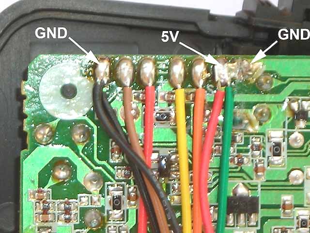
The diagram shows you the original circuit and the modified circuit. The circuit board photo shows where you can access 5V and ground nodes. Be careful not to flow solder from the 5V and ground nodes that are right next to each other. |
|
|
|
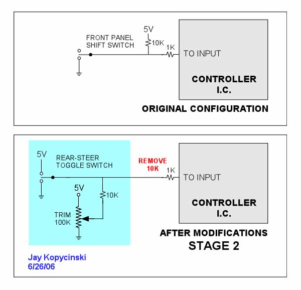
STAGE 2
For this steering setup, we also want the input node sitting at about 2.5V, and then switching to 5V or ground to turn left or right. To do this we'll install a toggle switch (three-position switch) that has a center-off position. You can choose a spring loaded one that returns to center when released, or choose one with no return. (Direction can be reversed, if needed, in the radio menu.) We will also add a 100k ohm trim pot and 10k ohm resistor (1/4 watt is fine) as shown below.
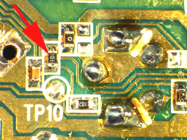
This mod also requires the removal of a 10k ohm chip resistor as shown by the arrow in the circuit board photo below. You will need a small tipped soldering iron and be very careful of adjacent components and traces.
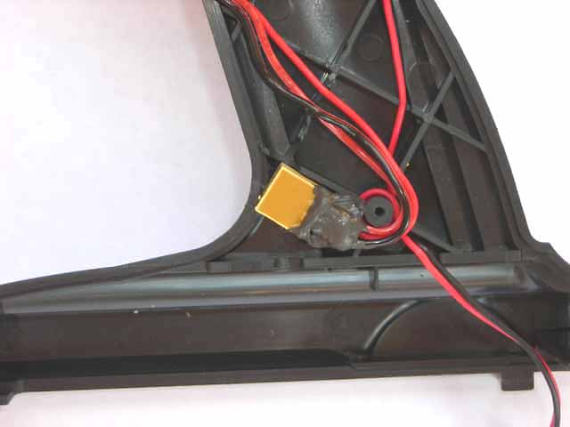
The diagram shows you the original circuit and the modified circuit. The photo below also shows how I mounted a 100k ohm trimpot in the base of the radio. I used a little RTV silicone to secure the wires and hold the trimpot in place. A small hole drilled in the radio case allows access to the adjustment screw. |
|
|
|
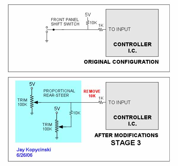
STAGE 3
For this steering setup, we also want the input node sitting at about 2.5V, and then sweeping towards 5V or ground to turn left or right. To do this we'll install a 100k ohm pot. (Direction can be reversed, if needed, in the radio menu.) We will also add the 100k ohm trim pot and 10k ohm resistor (1/4 watt is fine) as shown below.
As shown in Stage 2, this mod also requires the removal of the 10k ohm chip resistor shown by the arrow in the circuit board photo above. You will need a small tipped soldering iron and be very careful of adjacent components and traces.
The diagram shows you the original circuit and the modified circuit. The pot to the left is a panel mounted unit used to control steering. The pot to the right is the same trim pot shown in Stage 2.
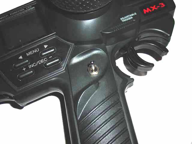
The photo of the front of the radio below shows a spot (although tight) where I found I could mount the small panel pot. In the case of my radio, I actually have capability to have simple switched rear steer or fully proportional. I simply added one more toggle switch to choose between which input control I send to the circuit board. |
|
|
FINISH & REASSEMBLY
You'll need to route the wires within the webbing in the radio case and you will probably have to cut some additional slots to do so. Reinstall any of the little plastic switch pieces that came off the on/off or trim adjustments. Reconnect the battery tray harness and reassemble the radio case with the seven/eight screws. Be careful that all the wiring is routed so it does not become pinched anywhere inside the case.
Enjoy the new independent rear steer!
-Jay Kopycinski |
|
|